Providing sufficient thermal energy is a fundamental requirement to successful AD operation. This primer reviews temperature requirements and methods to attain and maintain recommended values.
Kevin Jankowski
BioCycle May 2013, Vol. 54, No. 5, p. 36
Operation of anaerobic digestion (AD) plants is dependent on many variables that have been popularly categorized by primary requirements including pH, nutrient levels, temperature, mass transfer, retention time and carbon loading. Optimum ranges for the various parameters to achieve successful operation of an anaerobic digester have been thoroughly described in the literature. This article focuses on the temperature requirements of AD and methods available to attain and maintain the recommended values.
 systems produce both thermal and electric energy. The unit selected is dependent on the amount of heat required and the goals of the AD facility.")
Combined heat and power (CHP) systems produce both thermal and electric energy. The unit selected is dependent on the amount of heat required and the goals of the AD facility.
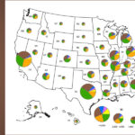
The most common temperature range employed in AD systems is the mesophilic, with a target of 98°F. In the contiguous 48 states, the highest mean temperature is in Florida at 71°F and the coldest is Maine at 40°F. Acknowledging daily and seasonal variations, any AD systems installed in the contiguous 48 states will require temperature control to function optimally. In most installations this will consist of heating, although a cooling system may be necessary depending upon influent temperature and ambient conditions.
Assessing Type Of Temperature Control
Temperature control systems range from simple and inexpensive to very complex. To assess the type of temperature control system necessary, it is imperative to perform detailed thermal calculations. The first step is to determine if the proposed AD system will be an energy-source or an energy-sink by evaluating the heat required for the feedstock compared to the amount of energy produced as biogas. This can be quickly estimated as a function of influent temperature (T1), operating temperature (T2), feedstock flow (Q) and COD concentration (COD):
[1] Energy Produced as Biogas = (Q*COD*C1)*(6.34*(491.67+T2)/
(586.67))*C2 = MMBTU/hr
[2] Energy Consumed by Feedstock = (T2 – T1) * Q * SG * SH * C3 = MMBTU/hr
• Temperature is in degrees F.
• C1, C2 and C3 are conversion
factors.
• SG is the specific gravity of the feedstock.
• SH is the specific heat of the feedstock.
For example, the results for a system treating 100,000 gallons per day of feedstock with 50,000 mg COD/L starting at 60°F would equate to:
[1] Energy Produced as Biogas = (100,000 gpd * 50,000 mg COD/L * 3.5 * 10^-7 L-lbs-day /mg-gal-hr) * (6.34 scf CH4/lb COD rem * (491.67 + 95°F)/ (586.67)) * 1000 BTU/scf CH4 = 11.1 MMBTU/hr
[2] Energy Consumed by Feedstock = (95 – 60° F) * 100,000 gpd * 1.02 * 0.91 *0.545 = 1.8 MMBTU/hr
• Energy Produced as Biogas, 11.1 MMBTU/hr > Energy Consumed by feedstock 1.8 MMBTU/hr.
Ambient heat loss calculations become much more involved and require knowing the AD tank dimensions and materials of construction and are a function of the local conditions. The ambient heat loss varies substantially based on the local conditions and must be evaluated to adequately size the thermal system. As a general rule of thumb, ambient heat losses account for approximately 30 percent of the total heat required for mesophilic systems. Ambient heat loss is calculated as a function of material properties (R), area (A), operating temperature (T2), and ambient temperature (TA) by:
[3] Ambient heat loss = (1/ R) * A * (T2 – TA)*C4 = MMBTU/hr
• C4 is a conversion factor.
At this point in an evaluation, it should be clear if the potential energy produced from the AD system exceeds the energy consumed (feedstock heating plus ambient losses) and the impact on operating costs. The next step is to determine how to get the heat into the AD system.
System Heating Alternatives

Figure 1. General energy balance for an AD with CHP
As shown in Figure 1, biogas can be utilized as a fuel source if the biogas meets the fuel requirements of the CHP system. Raw biogas must typically be conditioned to remove moisture and hydrogen sulfide. It is important to note that there are substantial energy losses when converting biogas to thermal energy, and when transferring that energy into the AD system. For a typical IC (internal combustion) engine CHP system with biogas used as fuel, approximately 35 to 40 percent of the energy is converted to electricity and 20 to 45 percent to thermal energy (45% if exhaust heat it captured). The remaining energy is dissipated from the engine and generator as heat that is not captured and a portion is lost in mechanical inefficiencies. The overall efficiency is about 80 percent with exhaust heat recovery. If sufficient thermal energy can be produced by a CHP, an added benefit is the generation of electricity. In comparison, a boiler only produces thermal heat and is typically 80 percent efficient. A boiler has a much higher thermal output than CHPs per unit of biogas consumed and is preferred if heat generation is the primary goal. One possible drawback is that if more heat is produced than can be consumed, the energy is wasted.
Table 1 depicts three case studies that utilized CHPs to meet thermal energy demand, i.e., the amount of heat required to maintain the operating temperature. These examples are all located in the Midwest. Case 1 and Case 2 produced enough heat strictly from the CHP unit engine block and lube oil during summer periods, but required exhaust heat recovery in the winter. The thermal energy demand in Case 2 exceeds the capacity of the installed CHPs. Additional thermal energy was captured from an effluent recycle heat exchanger and boilers were employed to increase the thermal capacity of the system.
In a CHP system, a closed glycol loop is employed to transfer the heat from the engine block, lube oil and exhaust into a single fluid. The fluid is pumped to a heat exchanger to transfer the heat to another closed loop used to heat the AD system. In a simple system with one AD and one CHP, the AD heating loop will be piped from the CHP directly to the AD heat exchanger and back to the CHP. Excess heat is radiated at the CHP unit.

Figure 2. A primary heating loop with secondary branches
Heat Exchanger Designs
A heat exchanger is key to transfer the thermal energy from the heating fluid to the AD. Heat exchangers come in many different designs. Common heat exchanger arrangements in AD facilities are the plate and frame, spiral, tube-in-tube, draft tube and internal coils. Equipment size, performance, solids handling and operation and maintenance (O&M) costs are typical criteria used to evaluate the heat exchangers. Some heat exchangers (plate and frame, spiral and tube-in-tube) pump a portion of the AD system sludge or feedstock through the heat exchanger and return it to the digester. Draft tubes and internal coil systems pump heating fluid through piping inside the AD system to radiate heat into the surrounding sludge. Pros and cons of the various designs include:

A spiral heat exchanger is used in systems with moderate solids concentrations. It offers high heat transfer efficiency, has a small footprint and is easy to maintain.
• Spiral heat exchangers are used in systems with moderate solids concentrations, offer high heat transfer efficiency, have a small footprint and are easy to maintain.
• Tube in tube heat exchangers can handle high solids concentrations with a good overall efficiency but have a large footprint. Spiral and tube-in-tube skid mounted heat exchangers are most common in wastewater treatment plant installations.
• Draft tubes and internal coils route a hot water loop through part of the digester infrastructure directly interfacing with the sludge. These systems have good heat transfer efficiency and a large footprint and are difficult to access if service is required. Redundancy or increased capacity in the design should be considered to ensure that adequate heat transfer is achieved. Internal coils are very common inside completely mixed AD reactors.
As previously indicated, the heat source — CHP or boiler — typically will maintain a thermal fluid system at 180°F. Appropriate controls must be employed to ensure that adequate heat transfer is proceeding without baking the sludge cake onto the heat exchanger surfaces, since this can happen when the temperature exceeds 130°F. The heat transfer rate decreases when this happens. If baking the sludge is unavoidable, utilization of redundant systems should be assessed.
Operations And Safety
Once the major components of the system have been defined, it is time to dive into the details of operations and safety. Critical components to monitor at each heat exchanger include the flow, pressure and temperature. These parameters allow the operators to track performance over time. For example, an increase in pressure drop across the heat exchanger while the flow is constant may be an indication that solids are depositing onto the equipment.
Safety interlocks should also be integrated into the system to protect the heating fluids. For example, the exhaust emitted from a CHP system is typically at 1,000°F. This temperature greatly exceeds the boiling point of water at 212°F. Water or water/glycol systems can safely capture the heat from the exhaust but must be continuously operated with the appropriate safety interlocks. If the fluid flow stops in the heat exchanger while the exhaust is operating, the fluid will vaporize and increase the pressure of the system, damage the fluid, potentially damage equipment and harm personnel. Monitoring the flow, temperature and pressure of the system will provide signals for the operator and PLC to initiate redundant devices, divert the exhaust flow, shut down the engine and warn personnel. Handling thermal fluids at temperatures greater than 120°F presents significant danger to personnel, as third degree burns are a possibility. Local codes, standards and NFPA guidelines should be referenced.
Summary
Providing sufficient thermal energy is a fundamental requirement to successful AD operation. Perform the following activities to ensure success:
• Spend time conducting thermal calculations early on to adequately design the system.
• Determine how much heat is required depending on the season.
• Evaluate if boilers or CHPs are needed to provide the required thermal energy.
• Determine the quality of the biogas and if conditioning is required.
• Evaluate and select the various heat exchanger options for your application.
• With all of the equipment defined, design the thermal fluid system making sure to include the appropriate instrumentation, interlocks, equipment redundancy and safety provisions.
Satisfying AD thermal needs will maintain substrate removal, energy production and the general performance of the system.
Kevin Jankowski, P.E., is an environmental engineer at Applied Technologies, Inc., a consulting engineering firm specializing in water/wastewater management located in Brookfield, WI.