New system installed at University of New Hampshire research farm captures both the thermal energy in the hot air generated by the composting process and in the water molecules of the vapor stream itself.
Matt Smith and John Aber
BioCycle February 2014
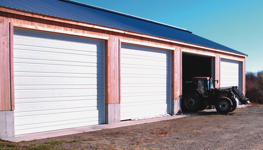
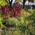
The aerated static pile composting operation at the University of New Hampshire’s Organic Dairy Research Farm is housed in a pole barn structure.
Over the past few years, increased attention has been given to heat recovery as a way to improve the economic viability of aerobic composting systems. One of the first composting facilities to explore the new generation of compost heat extraction technologies was Diamond Hill Custom Heifers in Sheldon, Vermont, using Agrilab Technologies, LLC’s Compost Heat Recovery System (see “Extracting Thermal Energy from Composting,” August 2006). Diamond Hill captures the metabolic heat produced by microorganisms during aerobic composting, through a negatively aerated fan system, and blows the hot compost vapor (110-170ºF) against the heat exchange system to heat water for radiant floor heating, feed preparation and sanitation of equipment.
While this facility was undergoing construction in 2005, the University of New Hampshire (UNH) Agricultural Experiment Station was in the final stages of converting one of its farms into the first certified organic dairy research farm owned and operated by a university. The current configuration of UNH’s Organic Dairy Research Farm (ODRF) includes a 100-head herd on bedded pack housing, approximately 140 acres of forage — 40 acres in certified organic pasture — and an additional 120 acres of woodlands, wetlands and farm infrastructure. During the organic certification process, one of the primary objectives was to address the manure management system, a conventional process that included a large anaerobic pile of manure solids and spent animal bedding that would occasionally be spread on the farm fields.
In addition to addressing this issue, researchers at the ODRF were beginning an extensive research endeavor on becoming a model farm for energy independence and nutrient management, with funding from USDA’s Sustainable Agriculture Research and Education (SARE) Program and the UNH-based New Hampshire Agricultural Experiment Station. During the initial planning process, it was determined that building a composting facility with heat recovery, similar to Diamond Hill’s, would address the manure, nutrient and energy issues in an integrated approach, while saving the farm thousands of dollars per year in energy from reduced hot water demands. This article describes the university’s journey in planning, building and determining the cost structure associated with this research facility.
In 2010, the goal of building a research heat recovery composting facility at UNH finally became feasible. Prior to 2010, the estimated project cost was in the $250,000 to $300,000 range, which was well beyond what the research group could afford. The project was only able to move forward when a local farmer/entrepreneur donated the funds to build the research facility and feedstock mixing area. Individuals involved in the UNH project toured the Diamond Hill composting facility to look at the design and operations. During the tour, outside temperatures were in the 20s, yet the air in the back mechanical room housing the compost heat recovery unit was in the 80s, and the open-air calf barn receiving the compost-heated water through radiant floor heating was 50°F. Following this visit, the design process for the UNH research facility began, with construction starting August 2012 and facility completion in May 2013.
Facility Design
The UNH Heat Recovery Composting Facility, located in Lee at the ODRF, is an 8-bay aerated static pile (ASP) composting system. The pole barn structure is 96-feet long, 50- feet wide and 22-feet high (ceiling clearance), and sits atop a heavily insulated concrete pad that has four inches of rigid foam insulation below it. The facility composts 90 tons of farm residuals/month (manure, spent animal bedding, waste feed, hay and woodchips), but has the capacity to compost any type of organic material. It can handle up to 400 tons/month of feedstock, should a shorter compost residence time be utilized.
Within the concrete pad are 16 recessed aeration lines made of 4-inch schedule 40 PVC pipe. Each line extends 30 feet into the main composting floor, and 2 feet into the back mechanical room through the push wall. To supply oxygen to the microbes in the compost, the aeration lines are set up in pairs, with each bay having two lines spaced 4 feet from one another. Each line has half-inch diameter holes drilled one foot from one another. Wooden cover plates with three-quarter-inch holes drilled 6-inches apart are placed over the lines to prevent compost fines from being sucked into the aeration system. When installed, the cover plates rest a half-inch below the floor surface, facilitating compost removal with a front loader.
Behind the entire length of the back push wall is the mechanical room, where the aeration fans, monitors, controls and heat exchange systems are located. Upon entering the mechanical room, the 4-inch aeration lines are connected to a butterfly valve that connects to an 8-inch diameter PVC pipe. Within this section of pipe is an 8-inch inline duct fan that pulls oxygen through the compost pile. Each bay has its own inline duct fan.
The hot vapor pulled from the compost pile is sent into an upper 10-inch diameter PVC network that connects to the Agrilab Isobar® Heat Exchange System. In a typical ASP composting facility, this heated vapor would instead be sent to a scrubbing/biofiltration system that may be under thermal stress, or exhausted to the atmosphere, wasting all the potential heat.
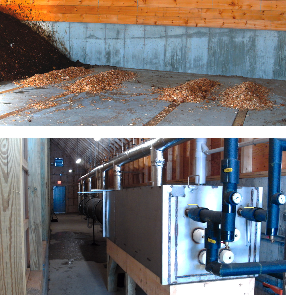
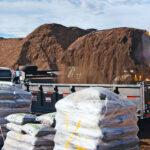
Aeration lines in the composting pad (above) are covered by wooden plates (with holes drilled in) and wood chips prior to loading feedstocks for composting. Each line extends into the mechanical room, which houses the compost heat recovery unit (left) supplied by Agrilab Technologies.
Heat Capture And Heat Exchange
Unlike some past heat recovery composting projects that are limited to either direct conduction between compost and buried pipe, or utilization of only the hot air in the compost vapor stream, Agrilab’s heat recovery unit captures both the thermal energy in the hot air and in the water molecules of the vapor stream itself. This has an important implication as only 13.4 percent of the heat generated within a compost pile is contained in the hot air, while 63 percent of the energy balance is in the hot water vapor, with the remaining heat being lost from the pile through natural convection and radiation (see “Control of Heat Generation During Composting,” January 2005). Although direct utilization of hot compost air is possible, the potentially harmful gases within it require use of a biofilter or an air-to-air heat exchanger, and are typically limited to horticultural applications. Instead, the Agrilab system is able to warm water from both conduction (hot air blown against the exchanger) and the latent heat of condensation and vaporization from the phase changes occurring within the heat exchanger itself. The end result is a much more efficient compost heat recovery system that has utility to all applications requiring hot water.
The UNH heat exchange system operates by blowing compost vapor (110-170°F), against an array of two-phase super-thermal conductor heat pipes, which were developed by a Canadian company named Acrolab. The six heat pipes (Isobars) are 30-feet long, with 22-feet contained within a 24-inch diameter vapor duct,and another 8-feet contained within a 295-gallon water tank. The Isobars provide thermal uniformity across the entire length of the pipe, meaning if one end is heated, the energy is immediately distributed evenly across the entire length of the pipe (Acrolab 2013). More specifically, when compost heated vapor is applied to the evaporator side of the pipe (portion contained within the 24-inch diameter pipe), the refrigerant inside the Isobar heats up and vaporizes. The vapor stream within the Isobar travels up the pipe, condensing on the cooler side, releasing its energy in
the bulk storage water tank through the latent heat of condensation. After condensing, the refrigerant is returned to the warm end of the pipe through gravity, repeating the process without any moving parts (Figure 1).
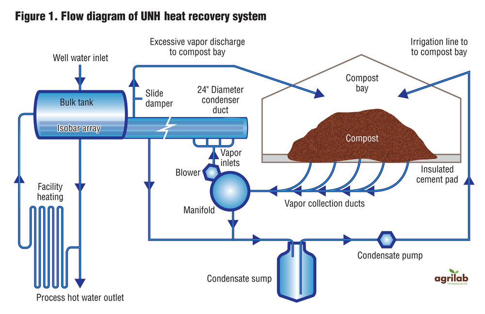
Figure 1. Flow diagram of UNH heat recovery system
Heat Utilization
Over the past six months of start-up operation, the UNH heat recovery system maintained the 295-gallon water tank at an average of 100°F. A loop of insulated pipe circulates this hot water at 6 gallons/minute to preheat water for the milk-house boiler. This water temperature is directly dependent on usage, with the temperature fluctuating depending on the daily farm needs in the milk house. It is expected that the average bulk tank temperature will increase by at least 20°F, as the reported average temperature includes data from the start-up phase, where only a portion of the composting facility was loaded and the heat recovery unit was not yet insulated. Additionally, a few of the composting bays were loaded with old material that came from the past anaerobic manure pit. Because this material was already substantially decomposed, there was less available decomposable substrate, meaning a smaller microbial population and less heat production.
Temperature in the bulk tank is also expected to increase over time through various research experiments on increasing heat production from the compost. The use of insulated, yet breathable compost fabrics, are currently being tested for increased heat production and capture. For reference, the much larger facility at Diamond Hill maintains an 800-gallon tank of water at 90° to 146°F, but composts three times more material than UNH.
System Cost And Payback
The total project cost of the UNH heat recovery composting system was $538,000 and was purchased from funds originating from the private donor and partial funding from the New Hampshire Agricultural Experiment Station. The project cost included site preparation, the compost building, feedstock mixing pad, the heat recovery unit and labor. This cost is substantially higher than if a nonresearch or noninstitutional owner were to build the facility, as the ORDF site is university-owned and was engineered to obtain approvals necessary to meet the stringent codes and long-term building requirements of the institution. Extra costs also occurred due to the research focus of the facility. If a compost operator were to build a similarly sized facility, and do a majority of the labor and materials purchases independently, it would be very possible to have the same composting system for under $300,000. For reference, the Agrilab heat exchange unit with technical support cost UNH $55,245, roughly 10 percent of the total project cost. An existing composting operation with aeration systems could add heat recovery for a fraction of this cost.
The payback period for this type of heat recovery project depends entirely on the current infrastructure at the composting site, and whether additional machinery, buildings, concrete pads, etc. need to be purchased/constructed. The payback period is also dependent on the volume of compost to be sold off-site, and the hot water demands for the heat exchange system. Due to the multiple site-specific variables between operations, payback periods have to be assessed on an individual basis. However, the UNH compost research group has developed an extensive cookbook-style report on how its facility was built with cost structure, materials list, and detailed cost-saving information on how to build a similar-sized facility for under $300,000 (Smith and Aber 2013). The extensive cost analysis in the larger report should allow operators to estimate the cost and a potential return on investment. This report will be available on the UNH Cooperative Extension website and on our research group website at www.aberlab.net in the coming months.
Dr. John Aber is a professor at the University of New Hampshire in the Department of Natural Resources and the Environment and lead investigator for the project. Matt Smith is a doctoral student at UNH and manager of the composting facility. Brian Jerose and Jason McCune-Sanders of Agrilab Technologies LLC contributed to this article.
Special Note to Readers
Because the work at the UNH Heat Recovery Compost Facility is research-based, we strongly encourage compost operators to contact us through the project website (www.aberlab.net), whether it is for more information or to schedule a visit to the site. We are eager to expand the network of heat-recovery composters and are always willing to provide insight on what we have learned throughout the building and operating phases of our heat recovery compost facility.
References
Acrolab. 2013. Isobar heat pipe. Available from www.acrolab.com/products/isobars-heat-pipes.php
Agrilab Technologies, LLC. 2013. Heat capture and aerobic composting: Renewable thermal energy technology. Available from www.agrilabtech.com
Smith, M. and Aber, J. 2014. Heat Recovery from Compost: A Step-by-Step Guide on Building an Aerated Static Pile Heat Recovery Compost Facility. Manuscript in preparation for publication.
Themelis, N.J. 2005. Control of Heat Generation during Composting. BioCycle, 46(1), 28-30.
Tucker, M.F. 2006. Extracting Thermal Energy from Composting. BioCycle, 47(8), 38.