The natural gas industry’s end-user piping design and regulations serve as guidance for biogas conveyance because both use smaller diameter pipes and operate at lower pressures.
Sara Martin and Craig Coker
BioCycle June 2016
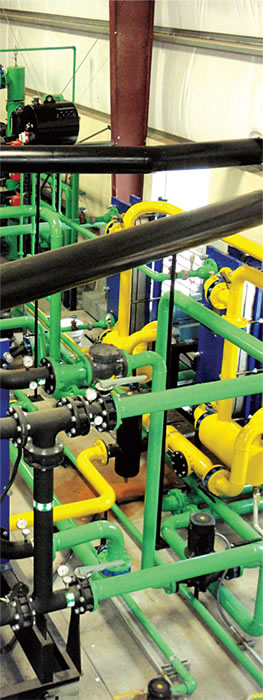
Photo courtesy of Regenis
The major differences between biogas and natural gas piping systems is the amount of treatment that each gas typically undergoes before conveyance, and the way the piping systems operate. Natural gas pipelines are heavily regulated, inspected and maintained. These regulations fall into two categories: major conveyance piping for distribution, and end-user (after the meter) gas piping. End-user gas piping design and regulations will be used for this article as a comparison to biogas piping because of the similarities — smaller diameter and operating at lower pressures.
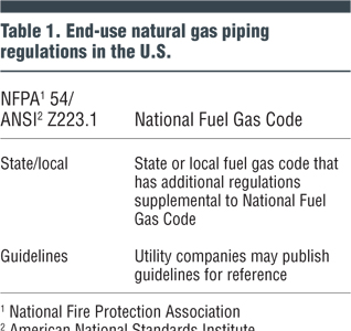
Table 1 provides an overview of regulations typically applied to end-use natural gas piping in the United States. Major distribution network pipelines have separate regulations (ANSI B31.8), which are not addressed within this article.
Biogas is harvested on a much smaller scale than natural gas under economic conditions and end uses that do not always warrant the amount of treatment that natural gas receives. Limited treatment often allows significant concentrations of moisture and hydrogen sulfide (H2S) to be present, which can present both safety and gas utilization concerns. Since biogas piping operates close to atmospheric pressure there is a risk of air entrainment, which is also a potential safety concern. Specifics of H2S, moisture and air are discussed later in this article.
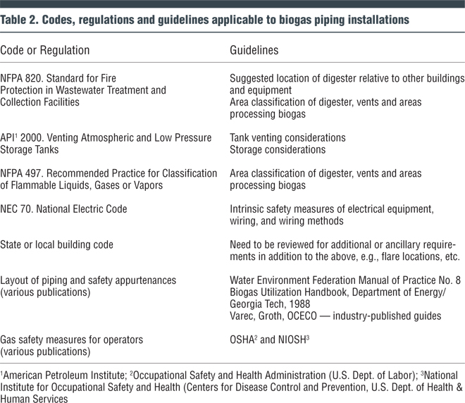
There are no codes or regulations specific to biogas piping in the United States. Depending on the owner of the system, biogas piping can be a secondary consideration during routine inspections and maintenance of the anaerobic digester system until a significant safety or performance issue has arisen. However, there are codes, regulations and guidelines (Table 2) that can be referenced for specific aspects of biogas piping installations. Also, if biogas receives treatment for moisture and other impurities and is pressurized up to higher pressures, then NFPA 54/ANSI Z223.1 can be used for further piping design after treatment and conveyance.
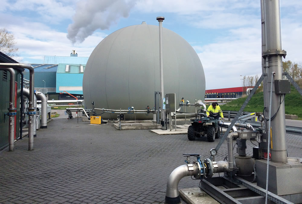
At the DRANCO Hengelo plant in the Netherlands biogas piping connects to the flare in the foreground, then the storage balloon in the rear, and the gensets on the left in the green containers. Photo courtesy of Organic Waste Systems (OWS)
Biogas And Natural Gas Comparison
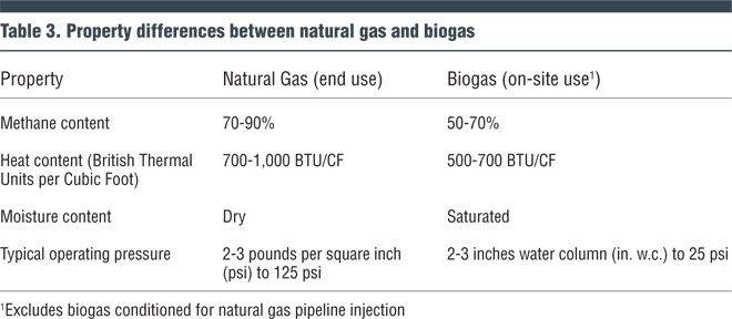
To understand the potential safety and performance issues of biogas, it is important to review the property differences between natural gas and biogas (Table 3). Natural gas piping can be operated at pressures much higher than biogas piping. There are many charts and guides for selecting the size of natural gas piping based on flow rate, temperature and pressure.
In comparison, biogas piping prior to conveyance (with a blower, compressor), or gas storage, is considered low pressure piping and is designed differently. The piping is typically sized to use the pressure of the anaerobic digester to “push” the biogas to the conveyance system and avoid pulling biogas out of an anaerobic digester at a faster rate than it is produced (and consequently, risk letting in undesirable air). Since most anaerobic tank vessels, storage systems and covers have physical limitations to hold high pressures, a majority of the biogas piping from these reactors operate at pressures slightly above atmospheric pressure (14.7 pounds per square inch (PSI)) from the reactor to the conveyance system. Landfills operate similarly to avoid pulling a vacuum on the headspace.
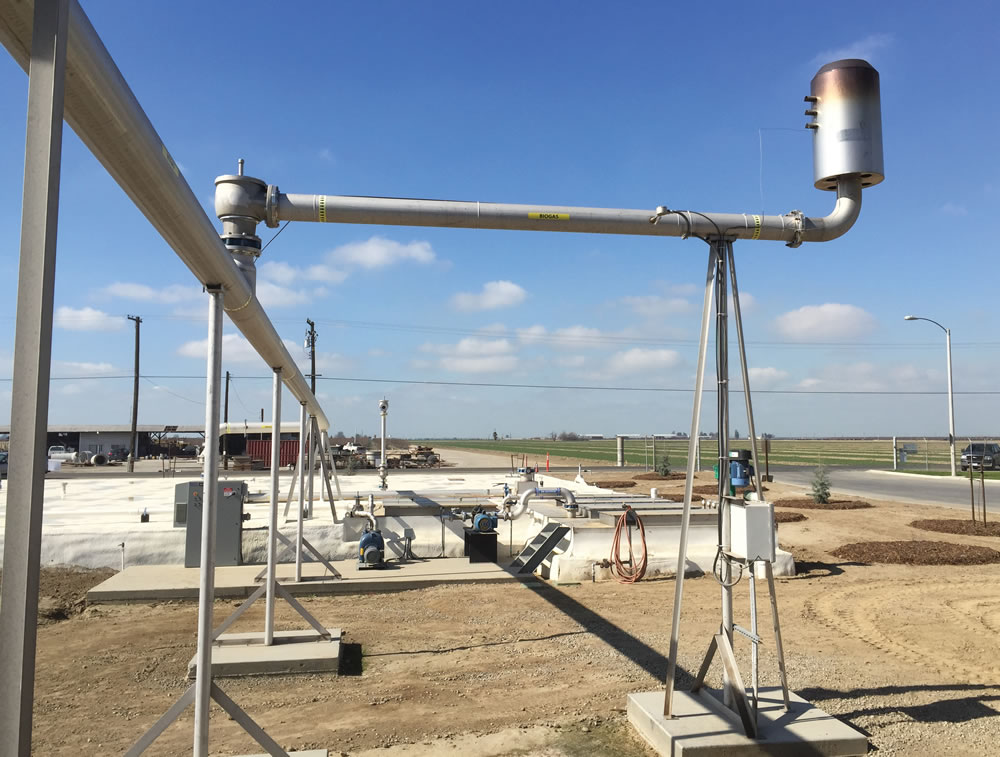
Any downstream spark sources, e.g., the flare (above), biogas blower or compressor, engine, etc., need an additional flame arrestor (or flame trap) properly placed between it
and the major piping system
to prevent flashback. Photo courtesy of Regenis
Depending on pressure required at the use point downstream of the storage or conveyance systems, the downstream biogas piping may also have to be sized as a low pressure system. Boilers, reciprocating engines and some microturbines can operate at a fuel inlet pressure of just a few PSI of pressure and therefore still operate at lower pressures than typical end user natural gas piping systems.
Biogas Piping Design Guidance
The properties of biogas outlined above make design of this piping crucial to protect from the following hazards that can occur:
Air (Oxygen) Entrainment
Biogas piping, storage and conveyance systems need to be sized and controlled to avoid pulling a vacuum at any of the vent points within the system. If this occurs, air can get entrained within the biogas system. Biogas produced under sealed conditions is devoid of oxygen and is not explosive because the methane content is too concentrated to ignite (above the upper explosive limit of 15%). However, once air is entrained the methane content can be diluted within the explosive limit and will contain oxygen, creating conditions that, if exposed to an ignition source, could explode or combust.
Flow and pressure monitoring and switches prevent this from occurring. If these instruments sense the pressure decreasing past a critical point close to vacuum conditions, conveyance devices should be slowed down with variable speed control or modulating valve and ultimately turned off to prevent further “pulling” of a vacuum on the system.
All drains and low point drip traps should incorporate an automated hydrostatic water level (like the p-trap in a sink drain) and the liquid trap maintained to prevent the pull of air in the system along the biogas piping. Adequately size the trap so it can drain under low pressure conditions. Routinely monitor and inspect these traps.
Flame/Spark Source
Anaerobic digester tanks, storage systems and landfills require vents to regulate pressure and prevent over pressurization and under pressurization of these systems from the biogas generation and conveyance, pumping, and other activities inherent to these systems. Because of this, there is an envelope around each vent that can contain the appropriate dilution of biogas with the explosive limit (5-15% methane) as well as oxygen. Exposure to a spark source near any of these vents could create an explosive condition.
Typical spark sources at digesters are lightning, cigarettes, tools (ideally nonelectrical spark-proof tools), flame torches (used to defrost piping), improperly rated electrical equipment (blowers/compressors/rotating equipment need to be spark-proof) and seal-offs, and even static electricity from clothing. Lightning protection, grounding measures and site safety plans for operations aid to mitigate spark sources. As an added protection, any vent areas should have conservation pressure/vacuum relief devices and flame arrestors to protect tanks, piping and storage systems from sparks. The pressure/vacuum relief devices will prevent escape of the tank headspace during normal conditions.
Flame arrestors or flame traps will help dissipate the spark source and/or a deflagration to prevent ignition of the remaining reactor headspace. Any downstream spark sources such as the flare, biogas blower or compressor, boiler, reciprocating engine, etc. need an additional flame arrestor (or flame trap) properly placed within the specified distance between it and the major piping system to prevent flashback within the piping system. These mitigation approaches also are applicable to ancillary vent systems where biogas will still be generated outside of the biogas piping system in potentially hazardous concentrations, such as anaerobic sludge holding tanks.
Moisture
Biogas is a completely saturated gas when it is released from an anaerobic digester, storage system or landfill. As this gas cools, the moisture condenses within the pipe and must be effectively and safely removed from the piping. If it is not removed, it can pool at low points restricting biogas flow. In small bore piping it can completely block flow and therefore passive piping smaller than 3 inches is not recommended except at drain points.
It is recommended that biogas piping have a minimum slope of 2 percent (or one-quarter-inch per foot per 100 feet of pipe). The initial drop of piping, points of pressure change, and/or major equipment should have a condensate/sediment trap for the higher rate of condensation that can occur at these points and to remove particulates that may be in the biogas. The condensation/sediment trap needs an automatic water trap to continuously drain condensate while preventing escape of biogas.
Install low point drains on every 200 to 250 feet of piping and at elbows. All other low points need drain piping with an automatic drip trap installed. Drip traps should have a water trap to prevent the escape of biogas from the system.
Moisture is problematic for biogas piping in colder climates. If not properly heat traced and insulated, it can freeze and block biogas flow. Biogas safety appurtenances such as flame arrestors, pressure regulating valves and flare ignition components can also freeze from this moisture and should be heat traced (intrinsically safe) and insulated. This also applies to in-line instruments, valves and low point drains. Heat trace should effectively cover all metal parts exposed to moisture.
Corrosion
Biogas contains hydrogen sulfide (H2S) and mercaptans that can condense in the form of weak sulfuric acid (concentration depends on how much H2S is in the biogas) within the headspace and piping causing rapid corrosion with incompatible materials. A material compatible with generation of weak sulfuric acid is recommended for any components in contact with biogas. Typical aboveground piping is metal; stainless steel is commonly used. Other materials that are not as corrosion resistant can be used as a cost-effective solution with some H2S removal technology applied upstream of this piping. Typical treatment methods to remove H2S and other impurities such as mercaptans are adsorption with iron media or granular carbon and/or chilling the gas (to remove excess moisture).
Plastic pipe is corrosion resistant but not recommended as this material does not have the necessary tensile strength and can be statically charged. However, high density polyethylene (HDPE) piping, suitable for natural gas service, can be used for buried piping as those two factors are less of an issue when buried.
Design for any biogas piping should include an extra safety factor in the hydraulic sizing for pitting and corrosion that can occur within the piping. Pitting and corrosion can change the internal diameter of piping, causing flow problems.
It is crucial for all safety appurtenances to be constructed of corrosion resistant material as well, including diaphragm materials. Gaskets and seals must be compatible as well as these will become leaks points if the gaskets corrode and degrade. Only spark proof plastics can be utilized for nonmetallic components such as fan blades. Make certain all downstream drain piping and drip traps are compatible with weak sulfuric acid.
Operators should monitor changes in biogas pressure within piping as these are usually the first signs of moisture build-up or corrosion. Visual inspection of the condensate can also indicate corrosion is occurring. A gas meter can be used at gasket and seal locations to detect escape of gases.
Pressure Regulation
As noted, pressure must be held within the anaerobic reactors, biogas storage and piping systems to prevent release of biogas to the atmosphere and aid in “pushing” biogas to the use point or conveyance system. This is accomplished using various pressure regulating devices throughout the system, including digester vents, storage system vents, flare system and use points. If any of these fail, an over pressurization event can occur resulting in a release at the weakest point of the system (covers, storage systems, etc.).
Conversely, biogas piping from an anaerobic reactor connected to a blower or compressor, if not sized or controlled properly, has the risk of pulling biogas from the reactor. If this negative pressure is not relieved it can also implode (collapse) at the weakest point in system (covers, etc.).
An emergency relief vent can be used as secondary protection to regulate pressure, but caution should be taken to release biogas from these appurtenances safely into an area rated for biogas release where operators or spark sources will not be present. Instrumentation can sense this has occurred and notifies operators that biogas is being released to the atmosphere outside of a controlled flare, and/or can shut down any blowers or compressors to avoid additional air entrainment in vacuum conditions.
Size pressure regulation and relief devices for the worst case credible scenario conditions and subsequent gas flow through them. The biggest risks and most failures are a result of either corrosion or freezing of these pressure relief devices and instruments that monitor or control pressure within the system. Refer to previous sections on corrosion, moisture control and freeze protection.
Leaks
Leaks are mostly from corrosion to piping, gaskets and seals within the system. Periodic sweeping of a biogas system with a gas monitor is recommended to detect any leaks. Safety appurtenances sometimes leak as diaphragm materials and mechanical components wear out or warp. Inspect these appurtenances one to two times per year, especially after winter conditions, to make sure they still seal off gases and do not vibrate in use, or “chatter.”
Any sampling hatches should have a stilling well that dips below the water surface to trap gases and protect operators during sampling and maintenance. In addition, having properly calibrated gas monitors on at all times near biogas piping and equipment is recommended.
As anaerobic digestion infrastructure grows and matures, more attention should be paid to the issues of safe biogas piping and transport. Industry groups should move to develop piping design standards into their best management practices guidance.
Sara Martin, P.E. is a Project Associate at O’Brien & Gere Engineers in Syracuse, NY (Sara.Martin@obg.com). Craig Coker is a Senior Editor at BioCycle and a Principal in the firm Coker Consulting (ccoker@jgpress.com).