Joerg Blischke
BioCycle April 2004, Vol. 45, No. 4, p. 49
One hundred miles west of Brussels – Belgium’s thriving capitol and headquarters of the European Union (EU) – is located “Westhoek,” the western part of the Province of Flanders. The early morning fog hangs over the meadows and farmland then slowly lifts, bringing into view wood piles and scaffolding used to provide support to one of the province’s most important crops and key ingredient of Belgium’s world famous beers: hops. Not far from here lies Ieper (Ypres in French), at one time the wealthiest and most powerful city and trading center of Flanders. Today, cemeteries enclosed by stone walls or hedges dot the landscape, a remembrance of the region’s more recent history. It was here, 90 years ago, that the most devastating battles of World War I took place, and the first time in history a chemical weapon – mustard gas – was used extensively. In just four years, the Great War in Flanders Fields left hundreds of thousands of soldiers from more than 20 nations dead, and the city of Ieper almost totally destroyed. Rising from the ashes, Ieper stands again as a viable city with its magnificent drapery/textile hall, the historic landmark at the central market square.
IEPER’S ANAEROBIC PLANT – PART OF BELGIUM’S WASTE AND ENERGY POLICY PROGRAM
A couple of miles from Ieper’s central market square, modern industrial structures group around two prominent 49 feet high, light grey painted digester tanks. This is the home of Flanders’ largest anaerobic waste treatment plant. With a total capital investment of 20 million Euro (€) (including costs for land, infrastructure and utility buildings), the facility has an annual waste treatment capacity of 55,116 tons and a daily capacity of 220 tons. The plant receives about 73 € per ton of delivered waste for further treatment. (1 Euro = $1.23)
The plant not only produces enough energy to meet its own thermal and electrical energy demand, but it also feeds more than 50 percent of its total generated electricity into the electric utility grid system. It provides enough “green” electricity for 2,000 homes. The positive environmental impact that the plant generates does not stop there. In tandem with its composting process, the plant produces 18,740 tons of high-grade compost when operating at full capacity. The matured compost quality is continuously tested to demonstrate conformity with the strict standards established by “VLACO”, a Flemish organization established to promote composting. While the price for produced compost is subject to seasonal fluctuations (with an average of 14 € per ton), a fixed price of 32.2 € per Megawatt-hour (MWh) of electricity that is sent to the electric grid system was established. A “green” electricity certificate scheme was implemented resulting in a current market value of about 98 € per MWh for “green” electricity.
This accomplishment can be primarily attributed to numerous legislative efforts. In the early ’90s, the Flemish Ministry of the Environment through its administrative organization “OVAM” (Flemish Public Waste Agency) initiated selective collection and composting of source separated organic waste (SSOW; in Europe, mostly referred to as “biowaste”) and green waste for the 6 million inhabitants of Flanders. Increase in waste diversion had become the agency’s main focus, reducing the tons of waste to be landfilled or incinerated. To stimulate the use of compost, a separate organization, VLACO – a cooperation between OVAM, inter-communalities, private compost producers, some cities and compost distributors and producers – was founded in 1992. Ten years later, OVAM adopted a waste implementation plan. With a final completion date of 2007, it will limit the amount of residual waste that can be disposed of to 330 pounds per capita per year. Since its peak in 1994, the amount of per capita waste disposal after separation of recyclable material has been in decline from 738 pounds to 423 pounds in 2000. In the same time period, the average amount of waste that was disposed of per capita per year in the U. S. saw an increase from 1,642 pounds in 1994 to 1,782 pounds in 2000 (January 2004 BioCycle, p.31).
Besides OVAM’s waste diversion efforts, another quite important aspect should be brought to the forefront: the implementation of a Renewable Portfolio Standard (RPS) for renewable energy (RPS in the U.S.: October 2003 BioCycle, p. 38). As a European Union member committed to meet the 1997 Kyoto Treaty emissions reduction standards of greenhouse gases, Belgium was obliged to follow the European Commission’s renewable energy directive and to implement a “Certificates of Origin” system for all renewable energy production by the end of 2003. Belgium established quotas/RPSs for its three regional governments – Flanders, Wallonia, and Brussels. The quotas are tradable, making use of the “green certificates.” While the certificates are not a policy measure, they serve as an instrument to accredit and register renewable electricity production and to facilitate trading. The “green certificates” are solely used to describe the “green quality” of the source that produces renewable energy and can be traded separately from the electricity as a physical commodity.
THE IEPER PLANT AND ITS PROCESS
As a result of regulatory requirements, the consortium IVVO (“Intercommunale Vereniging voor vuilverwerking van Veurne en Ommeland”), comprised of a dozen municipalities as well as private investors, formed a separate division to build and operate the waste treatment plant in Ieper. In the fall of 1999, companies throughout Europe were solicited to submit design and construction proposals for a turnkey anaerobic digestion (AD) and composting plant to include energy recovery by means of a combined heat and power station (CHP). The design criterion called for a processing plant with a nominal treatment capacity of 38,554 tons per year for SSOW (residential and commercial) and green waste on a 10-acre property (five acre footprint for buildings and paved roads). But as the waste generation studies for the IVVO region showed significant fluctuation throughout the year with its peaks during the summer months, the plant design also had to be flexible enough to handle the projected maximum annual capacity of 55,116 tons.
The request for proposal accommodated both wet and dry AD processes. The selection committee evaluated numerous proposals and in the third quarter of 2000 selected the preferred wet AD process offered by the German company Müell und Abfalltechnik GmbH (MAT) licensee of the BTA Technology (Biotechnische Abfallverwertung GmbH & Co KG), also based in Germany. Currently, two facilities are operating in North America that are using the BTA Technology with its license holder Canada Composting Inc. (see December 2003 BioCycle, p.39 and January 2004 BioCycle, p. 47.)
Construction began in 2001 and after some unexpected delays, the plant finally entered its “warm” start-up phase, the receipt of its first waste, in July 2003. As the amount of waste collected fluctuates, IVVO requested that the start-up phase last 12 months allowing sufficient time to verify the plant’s reliable operation and full waste treatment capability. In December 2003, the plant successfully passed its first performance test, and the first compost was produced in January 2004.
Throughout the entire project, the Flemish engineering firm Indaver, member of the consortium IVVO, has been providing engineering support and project management. According to Indavar’s Chief Engineer, Francies Van Gijzeghem, IVVO encountered some mechanical problems during start-up, but the difficulties have been rectified. He further noted that since the facility received its first waste in July 2003, it has proven operational flexibility in treating different feedstocks.
This waste treatment plant is Ieper’s fourth organics recycling facility. Two of them are immediately adjacent to the new site: a fully enclosed mushroom composting facility, and a green waste chipping, grinding and open windrow composting facility. The third facility, located just down the road, is processing chicken manure in a fully enclosed composting operation.
The Ieper waste treatment process can be described with the following eight steps: 1) Waste Receiving; 2) Mechanical Treatment and Conditioning; 3) Anaerobic Digestion; 4)Solids Dewatering; 5)Composting, Curing, and Storage; 6)Biogas and Energy Utilization; 7) Wastewater Treatment; and 8) Exhaust Air Treatment/Odor Control.
MECHANICAL TREATMENT AND CONDITIONING
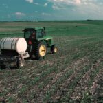
SSOW and green waste are collected with garbage trucks from residential and commercial generators and delivered to the waste treatment facility where it is dumped onto the tipping floor within the waste receiving hall. The receiving hall is equipped with automatic fast opening and closing doors to prevent odors from escaping the building.
A front loader picks up the delivered waste and feeds a bunker and dosing unit. This machine is not only designed to feed the trommel screen but is also equipped with a set of swinging knives that opens delivered garbage bags. As the collected material contains green waste with a fair amount of wood fiber not desirable for AD, the trommel screen functions as a crucial element in the overall process design. The trommel screen with a six-inch screen size separates the incoming waste into two streams: the screen overflow that is mainly composed of bulkier material greater than six inches primarily found in green waste, and the screen underflow with material less than six inches in size.
The screen overflow (ten percent on average of the total incoming waste) is sent directly to the plant’s composting section. The remainder, the screen underflow with its high organic content, is directed to the anaerobic fermentation process.
The screen underflow falls onto a chain scraper positioned directly beneath and across the entire length of the trommel screen and the initial bunker and dosing unit. The material is then distributed evenly into a deep bunker. A hydraulic driven traction conveyor floor, which is installed at the bottom of the deep bunker, and a series of screw conveyors downstream transport the material into two hydropulpers. The hydropulpers, designed to operate in an alternating batch mode, have a volume of 1,130 cubic feet each. Here, the waste is mixed with recirculated process water to a desired dry matter content between eight and ten percent while agitated intensively.
The batch operation takes 60 to 75 minutes and is comprised of the following intermediate steps: feeding the hydropulper with organic waste, dissolving and disintegrating the organic waste, draining the organic waste suspension, feeding the hydropulper with pretreated process water, raking off lightweight contaminants, and removal of heavyweight contaminants. More precisely, floating material such as plastic, textiles or wood (the light fraction) is raked out of the waste pulp and dewatered in a hydraulic press. Glass, metals, stones, batteries, bones and other heavy contaminants (the heavy fraction 1) are removed by a heavy fraction trap. With this effective and fully automated process, no hand sorting for contaminant removal prior to the digestion process is necessary.
The bottom of the hydropulper is equipped with a screen so that the organic waste suspension that is pumped out only contains contaminants (sand, fine gravel, shards of glass, small particles of metal, etc.) that measure less than 0.4 inches in size. But the removal of these contaminants doesn’t end here. To protect equipment installed downstream of the hydropulper from unnecessary wear and tear, and to improve compost quality, remaining finer particles of the pulp are further removed. The waste suspension is sent to a hydrodynamic grit removal system that is comprised of a charge tank, two hydrocylones and a buffer tank. With its specific design, the hydrodynamic grit removal process ensures that only a minimum of digestible organic matter is removed along with these contaminants (heavy fraction 2).
The dewatered light fraction is further stabilized and dewatered in two fully enclosed light fraction boxes. After 30 days, the dried material is screened in a mobile trommel screen. While the screen underflow is returned to the front end of the mechanical treatment, the screen overflow that is of high calorific value is used as a fuel substitute in waste incinerators or is disposed of. Both heavy fraction 1 (from the hydropulpers) and heavy fraction 2 (from the hydrocyclones) are temporarily stored in containers on-site. At present, heavy fraction 1 and 2 are disposed of. IVVO is currently investigating the possibility of using the heavy fraction 2 as construction material for pavements and roads resulting in an even higher waste diversion rate.
ANAEROBIC DIGESTION
The organic waste suspension, now virtually free of contaminants, is pumped from the grit removal system over to the two digesters placed outside. Here, in an anaerobic environment, the biochemical decomposition of the dissolved organic matter – acidification, hydrolysis, and methanization – takes place producing biogas with a methane rich content ranging from 50 to 70 percent by volume (v/v), and 65 percent v/v on average.
The two digesters, almost 49 feet in height and each with an active volume of 660,500 gallons for the organic waste suspension, can either run in series (two stages) or in parallel (single stage) providing the operator with additional operational flexibility. When connected in series, the biochemical decomposition is to a great degree separated: the first digester creates optimal hydrolysis conditions while the second digester houses the methanization. To create the most favorable hydrolysis conditions, a controlled amount of methanization reactor content is pumped back into the hydrolysis reactor. When connected in parallel, the entire biochemical process takes place simultaneously in both digesters.
This flexible process design allows the operator to find an optimum working point for biogas yield and methane concentration, hydraulic retention time, and process control and handling. The hydraulic retention time of the organic waste suspension in the digestion ranges from 12 to 15 days depending upon the amount and composition of the total incoming waste. Depending on the waste composition and the amount of trommel screen underflow, the biogas yield ranges between 2,564 and 3,847 standard cubic feet per ton of waste feedstock.
Both digesters are mixed continuously preventing sedimentation within the reactor as well as the formation of floating layers. Additionally, proper mixing ensures an even distribution of nutrients to the anaerobic bacteria populations and levels out temperature and pH fluctuations. For the Ieper plant, a mixing system with gas lances ending at the bottom of the reactors was installed. Part of the generated biogas is sent to gas compressors and is reintroduced into the reactor achieving thorough mixing even within the bottom section of the reactors. Compared with mechanical agitators, compressed gas mixing assures a complete degassing of the organic waste suspension with a high dry matter content.
Besides mixing with compressed biogas, the content of both reactors is also pumped through separate tube heat exchangers installed in the adjacent waste processing building. Both heat exchangers are charged with cooling water from the gas engines to maintain mesophilic process conditions in the digesters (93 to 98°F).
SOLIDS DEWATERING
After approximately 14 days, the digested residue (digestate) is pumped to the solids dewatering unit. A flocculant/polymer emulsion is added to the digested residue and then sent to three double pack sludge dewatering screw presses. The dewatering units handle the newly formed sludge polymer flakes carefully, and their energy consumption as well as their overall maintenance demand is small, keeping the operation and maintenance costs low. The filtrate is sent to the outdoor process water buffer where it is either reused (e.g. as process water for the hydropulers) or treated in the wastewater treatment system downstream. The dewatered digestate, with a dry matter content ranging from 22 to 35 percent and a standard set at 25 percent, is discharged onto a conveyor belt that is placed at the tail end of the screw presses. It is here that the trommel screen underflow is rejoined with the trommel screen overflow from the receiving hall. And, similar to the screen underflow, the screen overflow undergoes several process treatment steps well before both process streams are ready for composting.
The screen overflow material that leaves the trommel screen in the waste receiving hall is sent to a crushing device. This machine is comprised of a loading bunker and a screw drum crusher that breaks the material to well below three to four inches in size. If desired, additional structural material used in the composting operations can be loaded into the bunker at this point. Residual ferrous metals are removed with a permanent magnetic separator to protect the “Retruder” downstream. The “Retruder”, a thermomechanical device equipped with two screw presses in reverse motion, breaks down the fibres of the incoming material. As a result of defibration of the material, an ideal surface area is produced for the bacteria involved in the composting process. The defibrated material is discharged on a conveyor belt and mixed with the dewatered digestate. Due to its structure and high dry matter content, the defibrated material is capable of absorbing moisture, thus mitigating leaching or loss of water during the composting process after the dewatered digestate is admixed. Having received a desired porous structure, the mixed material – or raw compost – is now ready for the aerobic treatment step, the composting.
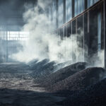
COMPOSTING, CURING, AND STORAGE
A front loader picks up the raw compost material and places it into one of the seven composting tunnels that are installed in a fully enclosed building structure and are operated in a batch mode. With concrete walls on both sides and at the end, each composting tunnel has two aeration channels embedded in the concrete floor. Cast iron covers with integrated air nozzels cap the aeration channels. The aeration channels have a dual purpose. They not only supply and distribute air equally across the entire length of the composting boxes, they also collect any leachate that may run off, which, isolated through an air-tight siphon system, is collected in a sump and sent to the process water buffer. The composting tunnels are equipped with a greenhouse-like roof that consists of a stainless steel frame and a semipermeable membrane cover. Once the composting box is filled with raw compost, roof and doors are sealed airtight and the controlled composting process can begin. The membrane cover creates a desired climate for the aerobic microorganisms in the composting tunnels, while the aeration control system, using an oxygen and temperature probe, monitors and adjusts the air supply and the temperature of the compost. All relevant parameters are continuously monitored controlling, as well as demonstrating, the thermophilic nature of the composting process and its resulting sanitation of the product through effective pathogen destruction. The laminate cover maintains a sufficient moisture level in the composting tunnel and acts as a very effective odor control barrier. (The membrane is permeable to air but impermeable to larger molecules such as odorous gases). With this composting process design, neither a sprinkling system for moisture control nor a turnover of the compost material is required, and the overall composting time is reduced to two to three weeks.
After this intensive and advanced first composting step, the material is moved into the curing building. Like the composting tunnels, the curing building is equipped with aeration channels, providing sufficient aeration for eight designated windrow areas. Each windrow area has two aeration channels connected to a timer controlled blower. After approximately six weeks of curing, the now matured compost with its desired moisture content is screened with a mobile trommel screen and brought into the fully enclosed storage building to await sale to its end-user.
BIOGAS AND ENERGY UTILIZATION
As described above, part of the generated biogas is used for sufficient mixing in the digesters. The remainder is sent to the combined heat and power station (CHP). In total, about 140 million standard cubic feet of biogas will be produced annually with an average methane content of 65 percent v/v. For proper design of the CHP, several aspects had to be taken into account. The design had to accommodate the seasonal fluctuation of the incoming organic waste. As a result, the CHP is equipped with four identical 12 cylinder gas engines and electric generator sets with an electric performance output of 300 kilowatt each in grid parallel mode. In addition, the CHP is also capable of running in island mode to continue operation during loss of grid power. As heat was needed during plant start-up, two of the engines are also designed to run on propane. In case of engine maintenance or other events, a medium temperature emergency flare is installed capable of flaring off any amount of biogas produced.
WASTEWATER TREATMENT
Regardless of the type of process applied to treat and biologically transform organically-rich matter, there is always a residual quantity of water. Therefore, wastewater treatment constitutes an integral part in Ieper’s organic waste processing system. The entire water effluents of the waste treatment process are stored in the process water buffer. While most of the process water is recirculated and reused, the surplus water undergoes additional treatment before it can be discharged into the adjacent canal.
In a first step, the wastewater is treated in a mechanical and biological system (MBS) followed by a second step where part of the outflow is sent to a vacuum evaporation and condensation system (VECS). The main outflow of the MBS is then blended with the condensate of the VECS to meet discharge limits. In detail, the MBS is comprised of a self-cleaning fine screen, a biological treatment with forced aeration and fixed film packing, and a clarifier for gravity separation of suspended solids. Some of the MBS and VECS effluents not used for blending and discharge are utilized in other sections of the plant, e.g. for rinsing. It should be noted that the electricity and heat required to operate the VECS is supplied in full by the CHP. The salt slurry from the VECS with a dry matter content of about 30 percent must be disposed of.
ODOR CONTROL
The receiving, waste processing, and composting sections of the plant are equipped with individual exhaust air collection systems. In the waste processing building, the exhaust air is not only drawn through openings in the air ducts across the building but also at individual collection ports at the equipment (e.g. hydropulper, light fraction boxes, dewatering screw presses) to further improve odor control. While the exhaust air of the receiving hall is exchanged twice per hour (air exchange ratio equal to two) the other two buildings have an air exchange ratio of one.
For moisture control and pretreatment, the collected exhaust air passes through a water-based conditioning and scrubbing system before it is sent to the biofilter. The conditioned air enters the four segments of the covered biofilter through a perforated plastic floor where it is distributed onto the biofilter bedding material. A combination of compost and bark mulch bedding ensures an optimal surface area for microbe colonization with high population densities, biological oxidation of the targeted volatile organic/odorous pollutants, and good water adsorption capability. An additional surface sprinkling system ensures a sufficient moisture level of the bedding material.
BENEFITS OF COMBINED METHODS
Adding source separated organics recycling to existing residential and commercial recycling programs further increases diversion of MSW. It not only preserves limited landfill capacity but also mitigates the generation of hazardous leachate and landfill gas. While organics recycling through composting is becoming ever more popular throughout the world, the composting process alone can neither recover the energy content of the organic matter nor can it meet its own operational energy demand. Combining anaerobic digestion with composting, as illustrated with Ieper’s waste treatment facility, provides numerous benefits.
Through its operation, the plant contributes to Flanders achievement of its 2007 waste diversion goal, meets its own energy demand, exports surplus energy as “green” electricity, and returns, with its produced high-grade compost, nutrient rich organic matter back to the soil. Furthermore, the facility makes its contribution to Belgium’s renewable portfolio standard by generating tradable “green” electricity certificates. The IVVO waste treatment plant is a leading example for a more sustainable waste management approach for the 21st century.
Joerg Blischke worked as a project engineer on the design and construction of the Ieper plant. He is now with the Environmental Consulting firm Metcalf & Eddy, Inc. in Santa Maria, CA, and can be reached at: joerg.blischke@m-e.com.