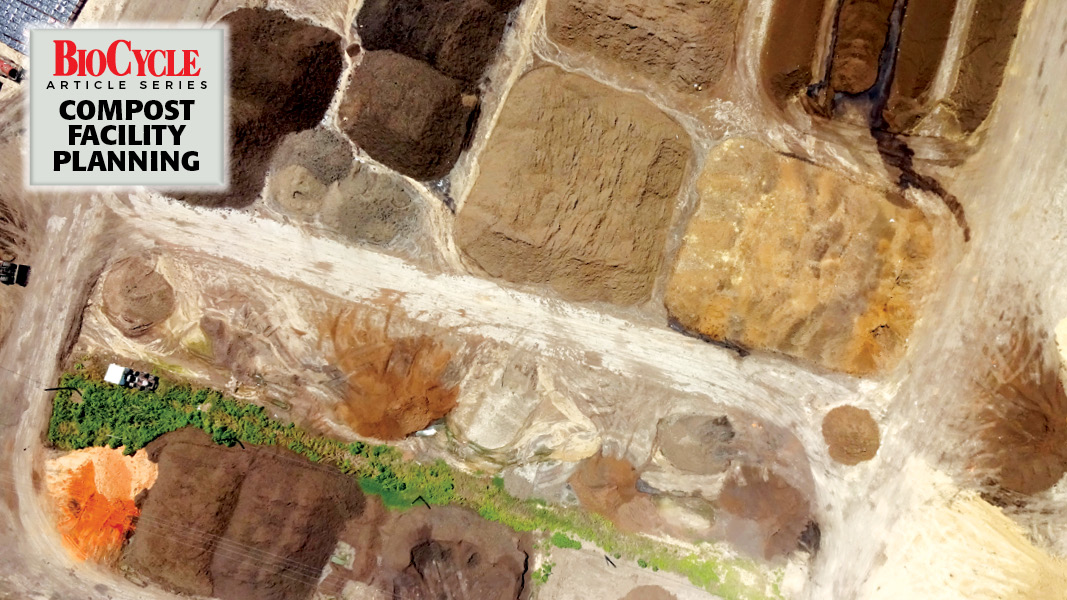
Top: New Earth’s composting facility in San Antonio, Texas
Craig Coker
Third of a series of articles on factors to consider when planning a new composting facility in the U.S.
Planning a new merchant organics recycling facility requires considerable thought and investigation. As the old adage goes, “Proper prior planning prevents poor performance.” This facility planning series is oriented to helping you think through the aspects of proper prior planning. Part I dealt with how to develop a Waste Capture Plan. Part II covered methods to assess the markets’ potential to absorb your compost and/or soils products. This article deals with methods for figuring out “How big should my facility be?”
Compost process design is a somewhat technical analysis of how you are going to convert the capturable wastes you identified in your Waste Capture Plan to meet the potential product demands you identified in your Market Assessment. Compost process design consists of three elements: Developing a mass-based composting recipe; Analyzing the volume-based footprint requirements for each step in the compost manufacturing process; and Arraying all those processing steps in a way that maximizes production at a minimal cost of materials handling. I did say this is somewhat technical.
Compost Recipe
Use of a well-crafted feedstock recipe ensures good process control that results in less malodors, shorter processing times and better product quality. The four main process control variables to be considered in developing a recipe are: carbon-to-nitrogen ratio (C:N), moisture content (%), volatile solids content (%) and predicted free air space (%). Not following these guidelines can have a significantly deleterious effect on process performance in composting. These variables are defined as follows:
- C:N is the ratio of the mass of total carbon in a pile to the mass of total nitrogen, and should be between 25 and 30 to 1.
- Moisture content should be between 50% and 55% (a little higher in the initial mix for aerated static pile composting).
- Volatile solids (VS) are the non-ash solids in a material and they represent the degradability of a feedstock (e.g. sludges/manures high, ash/drywall low). Total VS should be higher than 90%, although only about 70% to 75% of the VS in an organic material will be biodegradable.
- Free air space is the ratio of air volume less the air occupied by water to total volume in a pile and should be between 40% and 60%.
Assuming the feedstocks are acceptable from a metals and hazardous waste perspective, composters should obtain a representative sample of each and have the samples analyzed by a commercial laboratory. Ideally, each sample should be obtained from the point of generation, as this develops an understanding of the source of the waste, how it is generated and handled, and what potential exists for physical or chemical contamination. The analytical lab should be certified under the U.S. Composting Council’s Compost Analysis Proficiency Program for methodologies based on Test Methods for the Examination of Compost and Composting (TMECC). Samples should be tested for total nitrogen, total carbon, moisture content, volatile solids, pH, bulk density and soluble salts.
There are numerous computer-based compost recipe models available. I use an Excel spreadsheet that I developed years ago and will make available to those who request a copy. Keep in mind, though, that the laboratory analysis you get back on a feedstock for use in your recipe modeling will report Total Carbon. Not all carbon in a feedstock will be degraded by bacteria in the active composting phase. The carbon in plant tissues (which includes everything from wood chips to leaves to soiled napkins to last week’s brussels sprouts) is found in cellulose, hemi-cellulose and ligno-cellulose. Only the first two are degraded by the bacteria in composting; the ligno-cellulose is degraded by the fungi in curing.
Biodegradability Adjustment
As a result, recipes have to be adjusted for the biodegradable component in the carbon-based feedstock. One method for this is to adjust recipes for biodegradable carbon using a formula developed for anaerobic digestion process design (Chandler, 1980):
Biodegradable Fraction (B.F.) = 0.83 – (0.028) x Lignin Content of Volatile Solids (L.C. VS) Biodegradable-Carbon = Total Carbon x B.F. x Volatile Solids (VS)
An example of this analysis, using yard trimmings, is shown Table 1. Laboratory analyses of yard trimmings samples will likely differ due to the heterogeneity of the feedstock.
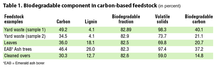
The net effect of this biodegradability adjustment is to raise the volumetric ratio of your carbon-rich amendments to your nitrogen-rich amendments from the traditional 3:1 to more like 4 to 4.5:1, which can be a challenge if carbon sources are limited in your region.
The bulk density (BD) measurements are used to estimate the free air space (FAS) in the mixture. Agnew and Leonard (2002) reported a linear relationship between bulk density and FAS:
FAScalc = 100 – (0.09 x BD)
where FAScalc is a percentage and BD is the wet bulk density (in kg/m3). This is a good approximation of FAS to use in these desktop analyses. Bulk density measurements also offer an easy way for loader operators to know how many buckets of each feedstock to add to the mix.
Footprint Analysis
A compost manufacturing facility is a volumetric materials handling exercise — volumes (e.g. cubic yards) of materials are moved from one step to the next and these volumes reside in one spot for each step for a period of time. This requires an analysis of how much area each step in the process will need at various points in the temporal evolution of a composting facility to reach its full capacity. An example of how to do a footprint analysis was covered in a recent BioCycle article, “Calculating A Composting Facility Footprint.”
Keep in mind that a manufacturing facility must have its outputs (products) move off the production line to make room for new inputs to be converted to products. In composting, this means finished compost has to move off-site at a rate greater than or equal to the volumes coming into the facility. It is very easy for these volumes of organic materials, in varying stages of decomposition, to accumulate at one or more processing steps due to equipment breakdowns, surges in feedstock quantities (e.g. the load of pumpkins coming in during the first week of November), staffing shortages, etc. This can “constipate” a composting facility, which can (and likely will) lead to odor problems, storm water runoff water quality problems, and a deterioration in employee morale.
When you do your footprint analysis, think through how and where constipation can occur and build in some extra “elbow room.” This will be important after you design your site layout (see below) and identify “squeeze points” in the materials flows through your proposed layout.
Site Layout
The most efficient site layout is a straight line, with the fewest number of materials handling activities during each step in the compost manufacturing process. Few sites can accommodate such pure linearity so site layouts become a balancing act between site constraints and optimized materials handling. Linearity doesn’t mean materials only flow in a single straight line; a linear layout could be “L-shaped” or “U-shaped.” You should avoid layouts where material flows cross over each other, as illustrated below. This former layout of a yard waste composting facility (which has since been modified and rebuilt) shows how feedstocks and materials move inefficiently around the site.
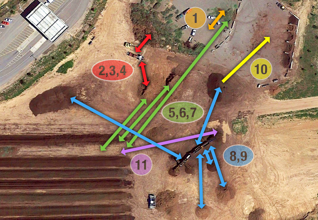
Figure 1. WIWMD Greenwaste Recycling Facility Materials Handling Steps 1. For curbside-collected material, separate grass and garden residuals from brush with rake on loader; 2. Push material toward grinder; 3. Grind material; 4 Pull material from grinder and put in pile; 5. Build windrow with materials from ground mulch, mulch overs, and grass/horse manure piles; 6. Turn windrow; 7. Tear down windrow; 8. Load screen hopper; 9. Pull material from screen conveyor belts and put in piles; 10. Move product from piles to load-out areas; 11. Move mulch overs back into compost windrows. Base image: Google Earth Pro 7.3.4.8642. Utah, USA. 41° 06’ 38.36”N, 111° 55’ 49.90“W. DigitalGlobe 2010
Compare that layout and materials flow to the example below. Materials flow in a U-shape around the bounding perimeter of the site.
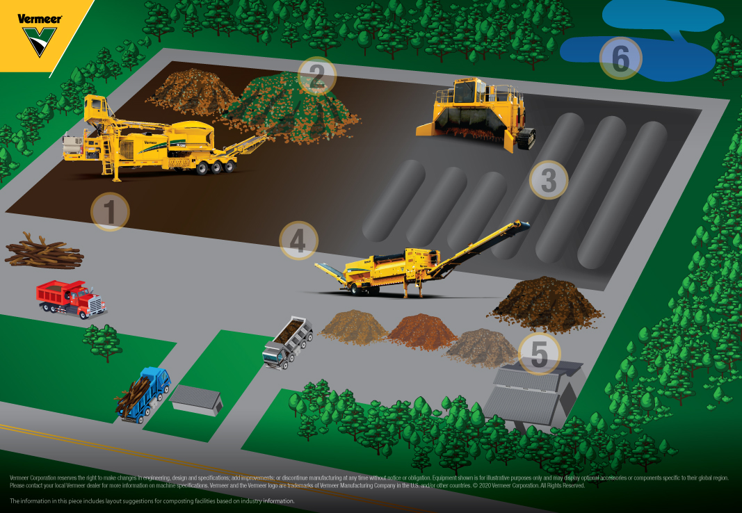
1. Drop-off; 2. Incoming material and grinding; 3. Composting; 4. Screening and finishing; 5. Retail; 6. Drainage pond and perimeter. Image courtesy of Vermeer
Using these tools to carefully create a compost process design can convey professionalism and competence to local and state approval authorities — a reward for proper prior planning!
Craig Coker is CEO of Coker Composting & Consulting near Roanoke, VA and is a Senior Editor at BioCycle CONNECT. He can be reached at ccoker@cokercompost.com.