BioCycle June 2007, Vol. 48, No. 6, p. 48
Compost, refuse-derived fuel, ferrous and aluminum are being recovered from a facility that processed 200,000 tons/year of mixed MSW in 2006.
Robert Spencer and Panagiotis Kalogeropoulos
BILLED as one of the largest mechanical-biological treatment facilities in Europe, 2006 saw the official commissioning of a 300,000 tons/year (design capacity) mixed municipal solid waste (MSW) processing facility in Athens, Greece to receive and process approximately one-fourth of the Attica region’s mixed MSW, biosolids and green wastes. Construction, which started in 1998, took four years to complete. The plant started commissioning tests in 2002 but was damaged by a landslide from the adjacent landfill in March 2003; in August 2004 a phased start-up was initiated.
During the reconstruction, a number of processing equipment changes were incorporated to accommodate a 15 to 20 percent greater volume of dry fraction materials that were arriving on the tipping floor, compared to 1995’s design assumptions that 45 percent of the waste stream would be paper and plastic, not 60 to 65 percent. (A future article in BioCycle will present more information on mechanical-biological treatment (MBT) and incineration projects in Europe, and the impact of modern consumerism and packaging materials on mixed waste processing facilities.)
The totally enclosed facility recovers refuse-derived-fuel (RDF) and compost, as well as ferrous and aluminum products. It is located in the municipality of Ano Liosia, adjacent to the Western Attica sanitary landfill. The state-of-the-art facility is owned by the Association of Communities and Municipalities of Attica Region (ACMAR)(www.esdkna.gr). The solid waste processing facility occupy 45 acres, including five buildings that comprise 12 acres. A transfer station and a medical waste incinerator are also included with ACMAR facilities. ACMAR operates collection programs for paper and hospital waste, with private haulers and municipalities collecting tires, motor oil, construction and demolition materials, and some household hazardous waste such as batteries. It is anticipated that the €60 million (current value) facility will reach its full processing capacity of 300,000 tons/year during 2007. It employs 220 persons in operations, maintenance, security and administration. Operating costs in 2006 (excluding revenue from sale of products) were approximately $50/ton. Two work shifts operate the plant five days per week; ACMAR is evaluating the benefits of going to a six-day/week operation considering the 20 percent increase in processing capacity. The primary source of the MSW is from residents, with some restaurant and commercial generators.
ENVITEC S.A. of Athens was the prime member of the design and construction team for the plant, and operates the facility with ACMAR. ENVITEC S.A. also constructed two other MSW processing facilities in Greece for the municipalities of Kalamata (40,000 tons/year), and Chania in Crete (75,000 tons/year). The facilities are considered MBT systems that address European Union directives to reduce landfill disposal, with the Western Attica facility projected to achieve 90 percent volume reduction, greatly extending life expectancy of the landfill.
WASTE PROCESSING LINES
Design capacity of the Athens plant is 120 tons/hour, achieved by three processing lines of 40 tons/hour each. Incoming garbage trucks are weighed and directed to an available discharge position. The reception hall includes three separate bunkers with 3,000 m3 useful capacity and six discharge positions each.
MSW is loaded by the grapple, ascends an apron conveyor, and passes under an overhanging bag-opener that is free to pivot when bulky items are encountered. Knives apply a shear effect on the plastic bags, exposing their contents to an inspection conveyor where bulky and unacceptable items are removed. A weighing conveyor provides data to the crane operator about how much material is being fed to the system in an effort to maintain even loading, or to shut down the conveyor in case of overloading.
Waste then enters the primary trommel screen, 12 feet in diameter by 33 feet long; screen panels have 7- by 10- inch rectangular holes. This primary trommel is equipped with knives and lifting blades that create a tumbling flow of its contents. To minimize blinding, the screen panels have blocking devices to trap plastic film, which is manually removed at the end of the day. The overs from the primary trommel, primarily cardboard and plastic film, go under a belt magnet, and are then reduced in size with an SSI shredder and conveyed to the RDF production unit. Unders are fed to a secondary trommel screen, 10 feet in diameter by 40 feet long; screen panels have 4-inch diameter round holes. The trommel screens, designed and built by ENVITEC, are hydraulically driven with adjustable speed (6-12 rpm) and variable slope (2°-5°).
ROTARY DIGESTERS
The 4-inch minus unders, which comprise the compostable waste fraction of the input MSW, are passed under a magnet and conveyed to rotary digesters for 24 hours of “prefermentation.” The composting portions of the facility include the aerobic, rotary digesters followed by an agitated bed, aerated curing system. The rotary digesters are 13 feet in diameter by 140 feet long with processing capacity of 120 tons/day. Bulk density of material going to the rotary digesters is approximately 30 lbs/cubic feet. Material is kept in the rotary digesters for one day, then processed through a trommel screen with 1-inch holes and then screen unders are conveyed to the agitated bays.
The rotary digesters, designed in cooperation with experts from Italy and built by ENVITEC at the Czech SKODA JS production facilities, are installed in the processing hall without any thermal insulation. At the end of each digester, a high-pressure blower distributes air into the material in the digester, countercurrent to material flow. The digesters are powered by 250 HP electric motors, and rotate at 0.5-2.0 rpm. The pinion rotates a large girth gear that is automatically lubricated with a spray system. The digester shell has a thickness of 1.5 inches under the tires, and reduces to 1.2 to 0.6 inches at other locations with lower load stress. Internally, the shell is protected by wear bars. The tires float on the shell and are dry-lubricated with graphite.
One challenge the facility has is operating the rotary drums at design filling depth due to higher than expected power demand. At this time, drums are being filled to about 40 percent while operators investigate a solution.
AGITATED BAY COMPOSTING
The composting portion of the plant was designed to cocompost the processed MSW with shredded yard waste and wastewater treatment plant biosolids, along with other organic fractions from the facility. There are six lines of in-vessel bay composting; each line has eight composting bays arranged in twin banks of four bays each, for a total of 48 bays. Roughly 60 tons/day of yard waste are brought to the facility and size reduced using a Willibald shredder. The facility has 500 m3 dewatered biosolids reception silos (three lines) equipped with Saxlund sliding frame extractors systems and metering screws. Except for some test runs, biosolids have not been regularly processed at the composting plant due to lack of agreement with the owner of the Athens wastewater treatment plant (WWTP). According to George Arvanitis, Head of MBT Plant Sector of ACMAR, a separate governmental authority operates Athens region WWTPs and “a price to be paid for composting biosolids has yet to be agreed.” He explains that they are in negotiations, and as with the unexpected increase in dry fraction MSW, the assumption that biosolids would be available has proven to be another operational and financial challenge.
Unders from the screened paddles of the RDF ballistics and yard waste, and overs from the final screening of compost (and eventually the biosolids) are mixed with the compostable fraction from the rotary digester in a mixing drum. Active composting and stabilization of the organic matter is achieved by eight weeks retention in agitated bays. Turning of each bay takes place every two or three days. The concrete walls of the bays, 10-feet tall and 300 feet long, form bays of 16 feet, 8 inches wide, filled with material up to 8-feet high. The floor is made of prefabricated slotted concrete slabs to provide aeration and leachate collection.
This composting system occupies the largest building at the facility, at 8 acres. For corrosion resistance, the building frame structure is epoxy painted, and the wall and ceiling panels are PVDF coated. Each of the six composting lines consists of a feeding system, a turning machine, and a discharge, dolly system. The feeding system directs the continuously incoming compostable material to the proper bay and fills each section by a set of two conveyors guided by a level detection device. In order to evenly distribute the organic material, and encourage even distribution of airflow through the materials, charging of the bays is performed in two or more layers, with the depth of each layer set individually.
The material is turned and advanced by a 40 ton, heavy-duty machine with a large rotor, a sloped conveyor, a pivoting chute, and a main carriage with several auxiliary devices. Each variable speed machine rotor is 5-feet 4-inches in diameter by 16 feet long, and has shear knives and scooping blades made of abrasion resistant steel. The large torque hydraulic drive is located inside the rotor. During turning, the scooping blades come within 1-1/2 inches of the floor of the bay. The hydraulically driven machine can move large quantities of material, up to 500 m3/hour. The pivoting discharge chute controls the movement of the material down each bay and can be varied between 16 and 20 feet, allowing for compensation of lost volume in the oldest material in the bay.
The turners move on rails mounted on concrete walls, with a creep speed of 0.5 feet/minute, and up to 2.5 feet/minute. Pressure sensors continuously adjust the performance of the machine based on pile height, compaction, and moisture content. Turning of each 300 foot bay is accomplished in approximately 2.5 hours. Auxiliary systems on each turning machine include power and signal cable reels, and hose reels for irrigation water. Due to the eight-week retention time, the aerated compost tends to dry so water is added via spay nozzles during turning. An on-board flow control valve adjusts water based on moisture data.
Conveyors from each of the six dollies discharge compost to a 1,000 foot long conveyor that runs along the side of the composting hall to the compost refinery plant. A weighing conveyor controls the bay discharge process.
The composting system has four aeration zones. The first three operate in negative aeration mode in order to reduce emission of corrosive gas into the building. Leachate is collected through pipes in the floor and treated at the facility’s WWTP. The fourth, positive aeration zone targets a moisture content of 35 percent for optimal performance of the compost refining unit. Operation of the aeration system is designed to maintain a temperature range of 55°C to 65°C for more than three weeks for pathogen reduction. Infrared temperature sensors are installed on each turning machine and are used for recording bay temperature profiles.
The odor control system for the composting building consists of 12 treatment units that use a multi-stage process in two cylindrical vertical scrubbing towers. Two odor treatment units are exhausted through one stack. Each unit has its own blower that moves up to 40,000 m3/hr. Three pumps recirculate scrubbing liquids. The liquid wastes are collected and pumped to a chemical WWTP. The scrubber system was designed by Larry Hentz with the U.S. firm of Post Buckley Shuh & Jernigan. It includes three tanks for sodium hypochlorite, sulfuric acid and sodium hydroxide. The tanks are seated in impermeable basins. Arvanitis reports that the odor treatment system is operating well with almost 100 percent removal of ammonia and hydrogen sulfide. “The closest residents are about 2,000 meters away, and there have not been any odor complaints,” he says.
System Recovery Rates
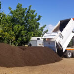
Compost refining consists of two lines. After eight weeks in the bays, compost feeds into a trommel screen (10 feet diameter by 40 feet long) with half- and 1-inch holes. Unders from the half-inch portion of the trommel are fed to a gravimetric system removing glass and small plastic foil pieces. The purified compost comprises the final product. Unders from the 1-inch portion are purified by another gravimetric system, and fed to a flip-flop screen. The unders are added to the final product while the overs are recycled to the mixer upstream of the composting unit. A compost pulverizing unit, followed by an automatic bagging, palletizing and wrapping line with capacity of 5 tons/hour, is located in a separate building.
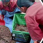
For each 1,000 tons of MSW processed through the facility, the following materials are recovered: 350 tons RDF; 200 tons compost; 25 tons ferrous; 1 ton aluminum. This leaves less than 250 tons of rejects to landfill, or about 25 percent of incoming MSW, which exceeds the European Union directive of 33 percent diversion. Arvanitis emphasizes that the facility recovery rate of 75 percent was based on six months of sampling, field sorting and laboratory testing by the National University of Athens (Chemistry Department) in cooperation with the Agricultural University of Athens and the Technical University of Dresden, acting as technical consultants to ACMAR. He also provided BioCycle with a detailed report on the changing waste stream, information that will be presented in a later article.
The university’s analyses demonstrated that the compost has glass and plastic content of less than 0.4 and 0.6 percent respectively. Compost is pulverized, and then sold in bulk, or bagged and palletized. The quantity of each type produced is based on market demand. Arvanitis says ACMAR is using the bulk compost as a vegetative capping layer for closed landfill cells and biofilter media, with some compost going to landscaping. Future uses include highway bank stabilization and sod growers. Table 1 shows the compost product analytical results.
Ferrous items separated from the processing lines are baled into 1-foot cubes, and have an average ferrous content of greater than 97 percent. Aluminum cans are similarly baled after hand-sorting to remove contaminants. Ferrous and aluminum are sold to local metal recycling industries.
RDF Production Plant And Markets
Primary and secondary trommel overs, with ferrous removed, are collected from the three processing lines and fed to the RDF production plant. The RDF plant is arranged in four lines. Processing starts with a ballistic sorting unit, which consists of five inclined screened paddles, 13.3 feet in width, a ballistic sorter to remove the lighter, “two dimensional” particles at the top discharge chute, and the heavier, “three dimensional” particles at the bottom of the chute. The sorter has adjustable speed (ballistic energy) and variable slope. The stream out of the bottom of the chute passes an eddy current separator recovering aluminum-based materials. The remaining flow is currently handled as a reject stream, with future plans for manual sorting of PET bottles and other recyclables.
The RDF stream contains paper, cardboard, plastic film and textiles, which are combustible, and a small percent of impurities. RDF markets in Greece are in development, and RDF will be produced in two types – shredded to less than 2 inches, and unshredded. Quantities produced of each type depend on the markets, with both types baled for transportation purposes. The bales are 4 cubic feet in size, with a bulk density of 650 kg/m3. A major cement manufacturer has agreed to take 70,000 tons/year of RDF, for a fee, for use in its cement kilns, replacing a portion of their fossil fuel demand. Arvanitis explains that RDF complies with an EU guideline regarding treatment of waste for use as fuel. ACMAR is also examining the possibility of co-firing RDF with lignite at power plants owned by the state electric utility.
The mixed waste processing plant was designed for a waste stream composition of 45 percent paper, cardboard and plastics. Tests conducted in 2006, however, showed that those fractions represented 60 percent of incoming waste. As a result, the waste processing lines handle more volume and the RDF lines are overloaded. Several modifications on the processing lines managed to maintain the capacity at a level of 36 tons/hour, but increasing capacity of the RDF lines is under examination.
Another challenge is the organization and management required to achieve daily processing of 1,000 tons of waste. Finding the proper human resources (employees who are specialized, experienced or trainable) and linking them all together, in a country without similar environmental facilities, proved to be a very difficult task. Plant operators also are managing the task of ensuring availability of spare parts, tools and consumables, since suppliers from Europe and the U.S. need considerable time to respond and support facility operations.
Robert Spencer, a Contributing Editor to BioCycle, is an environmental planning consultant in Vernon, Vermont. Panagiotis Kalogeropoulos is CEO of ENVITEC, based in Athens, Greece (www.envitec.gr).
June 21, 2007 | General