Adequate air delivery and distribution are key to an optimized composting process. Design considerations are provided. Part II
Craig Coker and Tim O’Neill
BioCycle July 2017
Part I of this article (“Aeration Floor Fundamentals,” June 2017) discussed how performance of the aeration floor is key to maintaining Best Management Practices (BMP) conditions during active composting. The aeration floor is also one of the more expensive elements of an aerated composting process. The initial capital cost is often the main driver when selecting an aeration floor technology. But if the facility is planned to operate more than 5 years, the full life-cycle cost should be considered along with the performance requirements. Another important element is matching the aeration floor to the type of aeration system (positive, negative, reversing).
These two considerations will be discussed toward the end of this article. First, it is important to review a standard set of performance metrics to use when evaluating any aeration floor design.
Aeration Floor Performance Metrics
Five main performance metrics to consider when designing and evaluating an aeration floor include: airflow uniformity, peak aeration capability, ability to manage leachate, ease of operations and maintenance, and longevity. Each is discussed below.
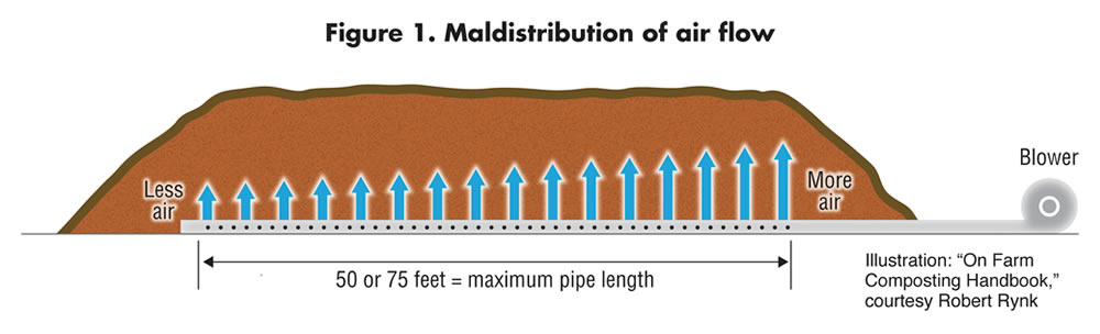
Figure 1. Maldistribution of air flow
Illustration: “On Farm Composting Handbook,” courtesy Robert Rynk
Air Flow Uniformity
Airflow uniformity refers to how evenly the forced air is distributed through the pile. The metric is “mal-distribution,” which assigns a percent variation of airflow across the aeration floor (example in Figure 1). While no design is perfect, one of the authors (O’Neill) has measured maldistribution in aeration floors ranging from a high of over +500 percent to a low of about +10 percent. Low maldistribution values (<+20%) more readily achieve consistent temperatures and oxygen levels throughout the pile (See Part I, BMP Indicators 1, 2, & 3). When air distribution is not uniform, significant areas of a pile’s biology will be inhibited by high temperatures, low oxygen, and uneven moisture levels represented by the low end of the BMP scale.
Relatively uniform air distribution can be achieved using a pipe-on-grade (POG) aeration floor in modest sized piles (i.e. less than 70 feet long) by observing a few simple design rules:
• Maximum spacing between pipes should be less than two-thirds the height of the pile
• Ratio of pipe length to internal diameter should be under 150 (e.g., for a 50-foot length of aeration pipe, the internal diameter of the pipe is at least 4 inches)
• Air velocities in the sparger pipes are below 2,800 feet/minute
• Total combined area of all orifices are under half of the cross-sectional area of the POG pipe
A simplified design template for designing POG pipes is presented on p. 32-36 in the On Farm Composting Handbook (Rynk, 1992).
Once either larger aeration floors with high aeration rates and/or in-floor aeration designs are considered, a numerical model should be developed to test and optimize the design. By varying the parameters in the model, the designer can balance air distribution uniformity and power use.
Peak Aeration Capacity
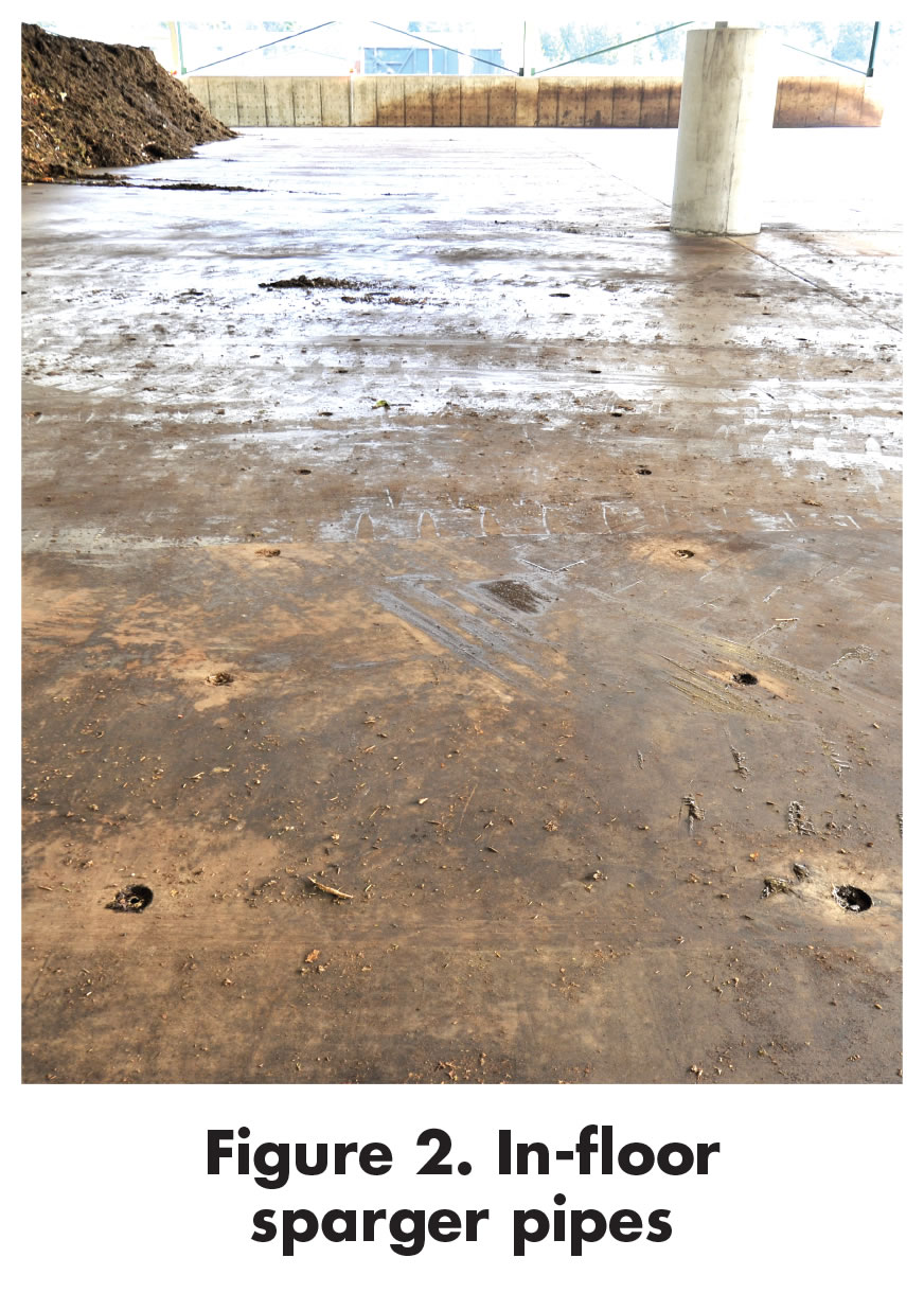
Figure 2. In-floor sparger pipes
Peak aeration capacity determines how quickly the temperature in a newly constructed aerated static pile (ASP) can be brought down to near mesophilic levels. Generally, food waste/green waste composting mixes start off with low pH due to the buildup of organic acids. Mesophilic range bacteria are best able to process organic waste at low pH. Thermophilic range bacteria are rate limited at low pH. ASPs with low peak aeration capability tend to remain above BMP compliant temperatures for the first two to four weeks with lasting negative effects. When early stage ASP temperatures are controlled by sufficiently high peak aeration rates, regrowth of mesophilic bacteria are able to oxidize inhibitory organic acids and raise the pH to within the efficient BMP range of 6.5 to 8, where more rapid stabilization can occur (see Figure 2 in Part I or in the online version of Part II).
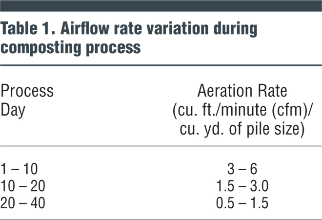
The peak aeration rate required to affect cooling depends largely on the amount of bioavailable carbon in the feedstocks; this tends to be highly variable. Generally feedstocks are most energetic early, but the heat output is not linear and varies somewhat randomly over time and certainly between batches (see Figure 2 in Part I). Table 1 provides design guidelines for peak aeration rates at different process stages. An aeration system capable of providing adequate peak aeration rates, if controlled with temperature feedback, can keep the process indicators of temperature, oxygen and pH near optimum conditions without overcooling the pile.
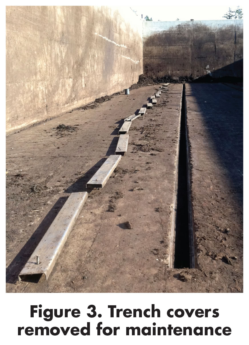
Figure 3. Trench covers removed for maintenance
Peak aeration rate is thus a key element of aeration floor design. The design goal should be to provide the peak aeration rates shown in Table 1 with uniform distribution of airflow, and without unduly high operating pressures that waste fan power. Lower pressure aeration systems conserve energy; as operating pressures increase, more fan power is required to move more air into the pile. A highly efficient aeration floor and aeration system can operate with fan pressures below 8.0 inches and still deliver aeration rates as high as 5 cfm/cy (cubic ft/minute/cubic yard).
Leachate Management
Leachate management is an important aeration floor design consideration since these liquids are highly odorous, carry solids that can clog pipes and sumps, and, if not drained, can saturate the bottom of the piles, inhibiting the biology as described above. The degree to which leachate must be managed depends primarily on precipitation amounts, types of feedstocks and regulations. Collecting these liquids is challenging, since water doesn’t flow under piles very predictably (compost itself forms dams and channels) and the entrained solids require regular cleaning/flushing from wherever they are captured.
All negatively aerated floors (where air is pulled through the pile into the floor) will collect leachate and condensate and require special attention to drainage design. Positively aerated floors leave most of the liquid to pool and run off of the working surface and require more auxiliary drains. However, even positively aerated in-floor systems will collect enough water and solids to be a nuisance and will eventually plug if the design doesn’t allow for cleaning or they are neglected. The bottom line is that leachate will accumulate in all aeration floors and in most applications there must to be a method to capture and control those liquids, and to have access to all below grade components to remove solids.
Operations and Maintenance
Ease of operations and maintenance is the key determinant of the aeration floor operating expenses (OPEX) and reliability. A well-designed in-floor aeration system will have much lower OPEX than a typical POG system, which requires disconnection/removal/replacement with every batch. Some hybrid POG systems are left on the pad connected and buried in a woody layer while wheel loaders work over the top. In the authors’ experience, these systems have been prone to serious airflow distribution problems, plenum and pipe clogging, and pipe damage (often undetected for long periods of time).
In-floor aeration system maintenance includes flushing and removing solids, and occasional repair of damaged surface floor elements caused by wheel loaders. These floors need to be easily accessible for pressure washing, scooping or suctioning to remove solids. For in-floor sparger pipes (example in Figure 2), this requires access at both ends of every straight run. For in-floor aeration trenches, the trench covers themselves must be removable. Fasteners for trench covers should be stainless steel with nongalling threads so that they can be serviced over the lifetime of the facility. An example of a trench with the covers removed for annual cleaning is shown in Figure 3.
Additional maintenance issues associated with a POG system include repairing pipe damaged during pile building and tear down activities, “ovalling” (misshaping) of pipes due to pile temperatures and pressures, and damage to the mechanism that connects the pipes to the aeration system. Large facilities that use POG aeration floors report needing almost one full-time operator dedicated to the repair and replacement of damaged pipe.
Longevity
Longevity is a key differentiator between an in-floor and an on-grade aeration floor. A well-designed in-floor system will last decades while POG systems have far shorter life spans.
The best choice for POG pipe material is heavy walled (DR 11 or 17) high-density polyethylene (HDPE). This material can handle high temperatures, friction, and even the occasional crushing by a wheel loader. The pipe ends should be heavily reinforced to withstand the stress of pulling pipe out from beneath a pile. The typical lifetime of an HDPE sparger pipe is 12 to 24 months. At very small facilities other pipe materials can be considered such as PVC (polyvinyl chloride), ABS (Acrylonitrile-Butadiene-Styrene) or thin walled HDPE, but these pipes should generally be considered disposable as they are not rated for the temperatures encountered and are easily fractured.
If an in-floor aeration system is going to deliver a long service life, suitable materials must be used in its construction. Buried pipe that will be exposed to elevated temperature and/or stress from above should be fused HDPE, which is tough, and not PVC, which is brittle. In addition, aeration components near the working surface need to be offset below that surface to not be damaged by wheel loaders, but not too deeply offset or they will collect material and plug more often. All metal components exposed to compost, leachate or exhaust airflows should be at least 304 stainless steel to hold up to the corrosive environment.
Aeration Floor Selection
A number of questions need to be answered in order to select the best value aeration floor for a given facility. The first is: how compliant with BMPs does the facility need to be? Each facility has unique performance requirements regarding odor control, regulatory compliance, and product quality. Part I discussed how the aeration floor design impacts the composting process variables that drive this performance. The other questions to be answered revolve around available land and throughput requirements, operational considerations, type of aeration system to be implemented, and, of course, the economics.
When space is limited with regards to throughput requirements, in-floor systems are generally the best choice since they require less floor space per ton than a POG system. POG systems require a significant area in front of the pile for the wheel loader to pull out a pipe. Unless small diameter pipe is used (and this reduces the workable pile length as described in Part I), the pipe-pulling area required is roughly the length of the POG pipe plus the length of the wheel loader.
Operational cost considerations drive the choice of aeration floor. These include aerated static pile size, labor availability, and requirements for leachate management. POG aeration floors are most successful at facilities with relatively short pile lengths, low cost labor, and modest requirements for leachate management.
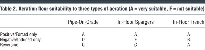
Compost aeration systems can be positive (air forced from the floor up), negative (air sucked into the floor), or reversing (alternating between the two). This choice is driven by need to control emissions (negative) and/or the desire to provide more uniformly BMP compliant conditions in the pile (reversing). Table 2 offers a qualitative assessment by the authors of how suitable the different floor types are for these three different aeration methods.
As indicated in Table 2, positive aeration is suitable for the three floor types listed; the positive pressure tends to minimize clogging in the sparger orifices and in-floor trench systems resist plugging by the pressure of the air and the more open nature of the trench air channels. Negative-only aeration systems are more problematic. The high air velocities at the orifices of both the POG and in-floor spargers tend to pull in solids and cause plugging. The in-floor trench, on the other hand, shows minimal plugging when used for all negative application. This is due to the much lower air velocities through the orifices and the great number of orifices compared to a sparger floor. However, even an in-floor trench system using only negative aeration requires a well-structured BMP mix.
Reversing aeration works somewhat better for both sparger variants since the floors can be set in positive while piles are being built and during initial settling to slow down plugging once the aeration system begins cycling from positive to negative. But even with positive aeration cycles, these floors will typically show measurable decrease in flow over a period of 4 to 8 days and require more frequent clearing of the orifices.
Understanding the full economic impact of aeration floor options requires a life cycle cost analysis. This relatively simple calculation uses estimated lifespan, and the costs of construction, operation (labor, repair, maintenance, electrical power) and financing in order to compare the Net Present Value of different options. A free calculator that can be adapted for this purpose is the Harvard Life Cycle Calculator, available at https://green.harvard.edu/topics/green-buildings/life-cycle-costing
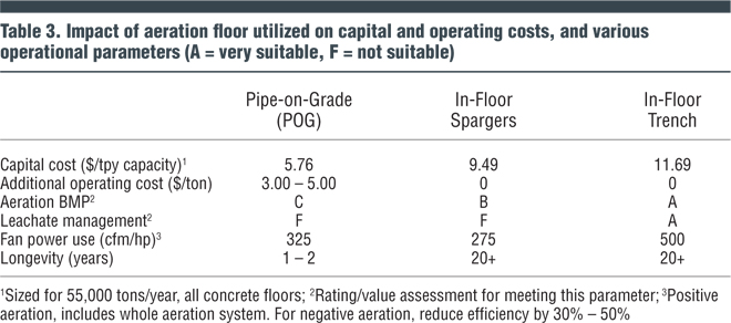
Table 3 summarizes the major economic and operational factors that should be considered when selecting an aeration floor. The cost analysis was part of a detailed design study commissioned to help a client determine which type of floor would best fit the business model and risk tolerance at a facility intended to compost 55,000 tons/year of source separated organics. This facility was in a dry rural area with yard trimmings as the primary feedstock; the client chose the in-floor sparger with positive aeration.
As increasingly challenging feedstocks are being diverted for composting in more populous areas, the need for more BMP-compliant composting processes is growing. The degree of BMP compliance is strongly determined by how well the design of the aeration system conforms to composting science. Making a well-informed selection of the aeration system and aeration floor better insures facility performance and long-term economic success.
Craig Coker is a Senior Editor at BioCycle and CEO of Coker Organics Recycling (www.cokercompost.com) near Roanoke VA. He can be reached at ccoker@jgpress.com. Tim O’Neill is the President of Engineered Compost Systems (ECS), an compost technology provider based in Seattle, WA. He can be reached at Tim@compostsystems.com.