This primer serves as an introduction for anaerobic digestion projects debating what type of gas upgrading system is right for their needs.
Paul Greene
BioCycle January 2018
Several powerful incentives are driving biogas generators to consider upgrading their biogas to meet standards for pipeline injection and vehicle fuel markets. Producing renewable natural gas (RNG) can create opportunities to monetize lucrative RIN, or renewable identification number, credits under the federal Renewable Fuel Standard and generate carbon credits under state supported low carbon fuel standards.
As each biogas project is unique it can be a challenge to determine the best gas upgrading technology for the given situation. Digester biogas can have varying levels of carbon dioxide (CO2) and elevated hydrogen sulfide (H2S) to address. Landfill gas and gas from covered lagoon digesters can have elevated nitrogen (N2) and oxygen (O2) levels and landfills and municipal wastewater treatment plant (WWTP) digesters have siloxanes that need to be handled.
Biogas Stream Considerations
Biogas is usually fully saturated with water vapor and typically has from 40 to 60 percent methane (CH4) and 40 to 60 percent carbon dioxide (CO2). Finding the proper technology or combination of technologies to upgrade the gas from these modest methane levels up to 99 percent methane can be challenging. The main treatment goal of gas upgrading projects is to get the CO2 removed from the biogas to create RNG with 1 to 2 percent CO2. Actual specifications will vary based on end use and the specific requirements provided by the gas utility off-taker.
Selecting an upgrading system that can reliably meet the CH4, O2, CO2, nitrogen and H2S specifications — and perform reliably day in and day out — is critical for a successful relationship with one’s gas off-taker. At times, such as at a new project site, technologies may need to be selected without having extensive biogas characterization data. Selecting a biogas upgrading system that is robust and can handle varying gas quality and quantity and stay within specifications is paramount.
The preferred design approach is to design for existing biogas streams that allow for maximum data collection for the upfront characterization of the gas. Generally, gas is pretreated to remove water and H2S before the gas upgrading unit. Where appropriate, users should consider drying biogas through aggressive refrigeration techniques or desiccant drying. Hydrogen sulfide can be effectively removed by several techniques, including ferric chloride injection in the digester, chemical scrubbing, carbon filtration, iron-based media filtration or biological desulfurization. Municipal WWTP digester biogas and landfill gas containing traces of siloxanes requires pretreatment through media filtration. In all cases the pretreatment system needs to be evaluated to ensure that it does not interfere with the gas upgrading system that follows.
In terms of water vapor content, biogas from a digester has just emerged from a warm, liquid process so it is fully saturated with water. Water vapor, or steam, is dissolved in the gas to its highest degree possible and thus the gas is extremely damp and humid, containing about 6 to 12 percent water by weight. Warm gas holds more water vapor than cool gas. Dew point is the measure used to describe the condition where steam starts to condense into liquid. High dew point (i.e., >70°F) gas is indicative of very humid gas that is acceptable to send to “wet” upgrading systems. Low dew point (i.e., <-20°F) gas is indicative of very dry gas that is acceptable to send to “dry” upgrading systems.
 Primary Upgrading Technologies
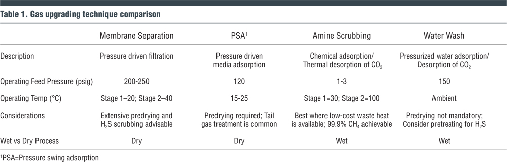
Four main technologies are used to create RNG from biogas: Membrane Separation, Pressure Swing Adsorption (PSA), Amine Scrubbing and Water Wash (or water scrubbing). These are usually deployed individually but can sometimes be installed in a series with one another, as needed for the given project requirements. Table 1 compares gas upgrading techniques.
The PSA and membrane systems are somewhat similar as both are “dry” upgrading systems that involve a physical separation of the CO2 and CH4 molecules based on the molecule’s size, driving pressure and ionic charge. Water wash and amine systems are similar in that they are both “wet” upgrading systems and involve separating the CO2 from the CH4 by solubilizing the CO2 in a liquid solution while allowing the CH4 to pass.
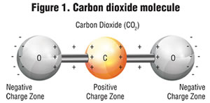
The pole charge and size of CO2 and CH4 molecules are key to how to get them to separate in a mixed gas stream. Carbon dioxide has a carbon in its center and an oxygen atom bonded to each side to make for somewhat of a linear shaped molecule as shown in Figure 1. The oxygen atoms have higher electronegativity thus hold electrons more tightly. This results in the CO2 having negative charges at the oxygen ends of the molecule. Carbon dioxide is more polar charged and a smaller molecule than CH4.
Methane has a carbon at its core and four hydrogens placed uniformly around the center atom. It’s a very uniform shape and has no appreciable ionic charge as shown in Figure 2. Carbon dioxide is a smaller molecule than methane. The difference in size, shape and charge properties allows for both physical and chemical separation.
 Membrane Separation
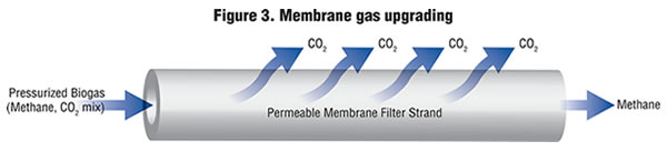
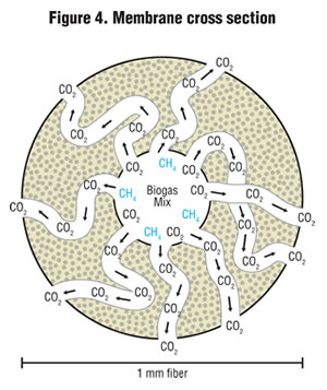 This technique uses polymeric membranes to separate the CO2 from the methane in biogas while under high pressure. Membranes are produced in long, thin fibers with a hollow center core. Typical fibers are about 0.5 to 1 mm diameter. Compressed gas travels down the length of the fiber and CO2, being a very ionically charged and smaller molecule, permeates through the porous membrane as shown in Figure 3 while the methane resists permeating and stays in the center core as it is larger in size and is very nonpolar in its ionic charge. Figure 4 shows a cross section of a membrane and how the CO2 diffuses through the porous membrane fiber.
Terms associated with membrane systems include:
Permeate: Gas that has travelled through (permeated) the porous membrane.
Retentate: Gas that is retained and collected at the end of the membrane fiber; this gas travelled down the path of the membrane lumen hole but did not travel through the porous membrane.
Selectivity: Ability of a membrane to predictably meet required separation performance expectations. It is a function of both the membrane manufacturer making a membrane of consistent high quality and the user ensuring the membrane does not get fouled by contamination.
 Thousands of fibers are bundled together into 4, 6 or 12-inch diameter tubes that are commonly 1.2-meters in length (example in Figure 5). To achieve greater than 98+ percent methane purity, two to three sequential stages of filtration are required: gas flows from stage to stage while increasing in purity. Dozens of tubes are configured together in parallel into “banks” based on quantity of gas to be processed. Each bank comprises a “stage.” Biogas can be both compressed into the front of the membrane system to roughly 200 psi and pulled out the back end with a vacuum pump to enhance performance.
Molecules that permeate the membrane quickly include both water vapor, H2S and CO2. The permeability of membranes can be manipulated by controlling the operating temperature. Cooler membranes have tighter pores and thus higher selectivity for smaller molecules like CO2. Running at warmer temperatures makes the membrane looser and accommodates higher flow rates through the membrane with reduced selectivity.
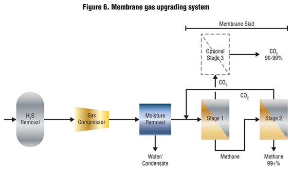
By balancing flow rates and temperature, engineered system providers configure the membrane arrays in a way that optimizes performance and cost. A common configuration includes discharging the permeate from membrane stage 1 and recirculating the permeate from stage 2 to the front of the system to maximize methane capture as shown in Figure 6.
In recent years membrane manufacturers have improved manufacturing quality, improved membrane selectivity and overall system methane recovery. These factors all lead to better overall system performance, improved economics and increased opportunity for long term success.
Design Features To Examine:
• For landfill gas or covered lagoon applications, separating nitrogen from methane is challenging with membranes therefore further gas polishing is required when there is a significant amount of nitrogen in the raw biogas. In addition, biogas oxygen levels can cause performance issues as membranes are not selective for separating oxygen. For example, sources of oxygen can be a less-than-airtight landfill or leaky covered lagoon, as well as leaking fittings on the suction side of compressing equipment.
• Common pretreatment is an activated carbon filter to remove H2S to <100 parts per million (ppm) and volatile organic compounds (VOCs).
• To be on the safe side, aggressively dry the biogas ahead of the membrane to be sure that VOCs have been removed to the greatest extent possible. The VOCs can irreversibly foul or compromise some membrane types. Drying can be done economically by refrigerating the gas to 40°F to 60°F and capturing the resulting condensate.
Benefit Claims Of System Suppliers Include:
• Low energy use and overall operating expense — roughly $1.00/million BTUs of gas treated
• Highly containerized designs minimize installation effort, footprint and time
• Very fast start-up — treated gas is ready in seconds
• Low operator attention required, roughly 30 minutes/day
• High gas purity; >99 percent methane is possible
• High gas yields, very low methane loss of <0.2 percent
• Over 10-year membrane life; Technology is rather new thus difficult to know exactly how long membrane lasts (though systems have been running for 10 years in the U.S. on original set of elements)
• Low maintenance requirement due to few moving parts
• Available guarantees include methane purity and uptime but generally not membrane life
Additional Available Features:
• Systems can be configured to produce recoverable CO2 by-product in a liquid form and sold to the food industry for ingredient use. Embracing this feature would make for an almost zero emissions system where all the feed gas was recovered as either pure methane or pure CO2.
• Gaseous CO2 emissions can be sent to greenhouses for plant farming or to other recovery system.
Two entities are involved in the supply chain of membrane upgrading systems. First, membrane manufacturers spin polymers into membrane fibers and bundle the membranes into modules. Second, engineered system suppliers put the membranes into skidded systems with the needed rack configuration, gas recirculation strategy, pumps, valves, instruments and controls.
Common lead times for installation of a complete membrane upgrading system are 9 to 10 months from order to start up.
Pressure Swing Adsorption (PSA)
 PSA is a batch process utilizing several vessels running in parallel under pressure. The heart of the process is an adsorptive media, similar to activated carbon, which separates gas molecules based on their molecular weight and size. Predrying the gas ahead of the adsorbers to about 5°C is required to keep the humidity out of the vessels to maximize their performance as dry adsorbers.
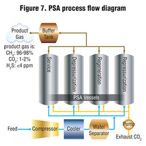
Figure 7 is a PSA process flow diagram. Carbon dioxide is preferentially adsorbed onto the media because it is a smaller molecule than methane and can permeate into the tiny pores in the carbon bed more easily and deeply. The methane goes through adsorber process columns relatively untouched while the CO2 is held behind in the media. The adsorption process is reversible thus the CO2 is eliminated during the regeneration cycle.
When a vessel has been saturated with contaminant gas, it is regenerated by reducing the pressure. At lower pressure, compounds are removed and desorbed from the media in a separate gas stream called “tail gas.” Common cycle time to saturation is 2 to 4 minutes. The tail gas is a low quality gas stream that contains the previously adsorbed compound like CO2, H2S, and trace methane. Each vessel alternates its mode of operation from service, depressurization, regeneration and finally repressurization before it returns to service mode. Vendor approaches include anywhere from 4 to 10 adsorber vessels to optimize performance and system economics.
Benefit Claims Of System Suppliers Include:
• Product gas quality of 96 to 98 percent methane
• PSA is the only gas upgrading technology that can separate oxygen and nitrogen from methane
• Can be provided as either primary upgrading system or polisher to other approaches when N2 or O2 removal is required, as in the case with landfill gas or leaky covered digesters
• No requirement for scrubbing water or scrubbing chemicals
• Small footprint and height requirements
• Able to handle some biogas impurities with relative ease
• Economical in a wide range of flow rates
Amine Scrubbing
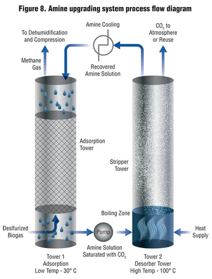
Amine scrubbing system uses a two-step approach to upgrading biogas. The first step is adsorption followed by a second step of stripping or desorption as shown in Figure 8. The amine portion of the scrubbing solvent molecule chemically reacts to the CO2 in the biogas to retain it in solution. A common chemical deployed as the scrubbing solvent is MDEA (mono di-ethanol amine). The methane fraction of the biogas passes through the packed tower reactor untouched by the scrubbing chemical. High methane purities can be achieved in the recovered natural gas (>99.9 percent).
In the second step, the scrubbing solution is heated to boiling to reverse the chemical reaction. The CO2 in the fully packed stripper tower is disassociated from the scrubbing solution and discharged. High CO2 purities in the off-gas can be achieved to accommodate potential for CO2 reuse. The regenerated amine scrubbing solution is then cooled and reused back in the scrubbing tower in a closed loop system. Systems run at a relatively low operating pressure of about 0.5 to 3 psig. This low-pressure design affords equipment and operational savings as compared to systems that run at high pressure.
Raw biogas H2S levels over 300 ppm are recommended to be pretreated by any of the desulfurization techniques mentioned in the beginning of the article. Feed biogas is pressurized slightly ahead of the first step by a blower.
Amine Scrubber Operating Conditions:
• Adsorber Column: pH = 11-12, Temperature = 70°F, Pressure = 0.5 psi
• Stripper Column: pH = 11-12, Temperature = 212°F, Pressure = 0.5 psi
Recovered biomethane is dehumidified through a desiccant dryer and then pressurized to supply the natural gas grid. Pressurization power consumption is lower than for systems that use gas compression ahead of the scrubbing system since just the recovered methane is compressed versus the total raw biogas flow in other systems. The heat requirement for the second stage regeneration tower is important to consider in overall system operating costs. An ideal application would be one where a steady, ample supply of waste heat was available, e.g. as from a combined heat and power (CHP) engine.
Amine technology does not offer appreciable removal of O2 or N2 for landfill gas or covered lagoon applications. A polishing step would be needed in cases where O2 and/or N2 specifications apply.
Benefit Claims Of Systems Suppliers Include:
• Low electricity usage — approximately $0.50/million BTUs of gas processed
• Thermal efficiency — 80 percent of heat is recovered and reused
• Greater than 99.5 percent methane capture
• Low usage of water and amine solvents because it is a closed loop system
• Wet process can minimize need for robust pretreatment. System handles VOCs, siloxanes and H2S
• Fully automated to minimize operator attention
• Flexible system that can easily turn down capacity if needed.
• CO2 off-gas is pure enough to recover for subsequent reuse
Amine systems are newer to North America but have an appreciable market presence globally.
Water Wash
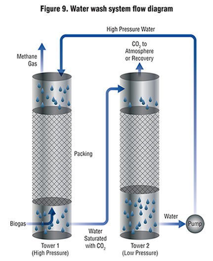 Water wash systems are a two-stage process much like amine systems (Figure 9). The first step is a high-pressure reactor column that works in a counter current fashion. Chilled water flows downward and biogas flows upward under high pressure (150 psig). Soluble gases like CO2 dissolve in the water, much like CO2 stays completely dissolved in a typical carbonated soft drink container. The second tower serves as a depressurization tower where pressure is released from the solution and CO2 degasses much like when pressure comes off an opened carbonated soft drink.
Makeup water is added when needed. Blow-down water is purged from the system to maintain desired pH and water quality.
This system is run as a wet process thus no predrying of the biogas is formally required but is recommended. Any H2S found in the biogas is adsorbed in the process. The H2S is purged from the system into the wastewater blow-down. Some suppliers, however, argue in favor of H2S removal ahead of the system.
As noted, the operating temperature is about 60°F and operating pressure is elevated at 150 psi in the first reactor. Proper component selection for this high-pressure operating system is paramount to meet the long-term rigors of a high-pressure working environment.
Water wash systems are effective at meeting stringent RNG specifications. Methane values of over 98 percent are readily achievable. As O2 and N2 are only sparingly soluble in these systems a polishing step can be utilized when aggressive O2 and N2 specifications apply and elevated levels are found in the feed gas. One prominent U.S. facility with a tight O2 specification, for example, has successfully deployed high temperature catalytic oxidation to meet the O2 spec.
Up to 1 to 2 percent of incoming methane can wind up in the CO2 gas waste stream. This off-gas can either be safely emitted to atmosphere or polished by thermal oxidation based on local permitting conditions.
Benefit Claims Of Systems Suppliers Include:
• Proven technology with years of run time in full-scale applications
• Cost competitive especially in larger sizes
• Modest operating costs
• Flexible, robust system that can be adjusted based on incoming feed
• Strong North American installation base
Performance data from a 1,600 SCFM biogas treatment system in North America shows effective performance with 98 percent pure methane in the RNG output with trace quantities of H2S (1 ppm) and O2 (<1300 ppm) as well.
Summary
Each of the upgrading systems are capable of meeting gas pipeline or vehicle fuel specifications either as standalone units or in combination with each other. Each project needs to be evaluated individually to properly determine the correct configuration and sizing of all the system components to ensure long term project success and at the optimum life cycle cost.
Paul Greene is a Senior Technical Advisor with CDM Smith, a top 5 environmental engineering company and construction firm with expertise in gas upgrading. He is a Director and Previous Chair of the American Biogas Council, Chair of the ABC RNG Working Group and holds a B.S. in chemical engineering. Mr. Greene has been providing his expertise to digester projects coast to coast for over 20 years. Mr. Greene would like to acknowledge B&W Megtec, Evonik, DMT, Unison, Puregas, Air Liquide, Newtrient and Xebec for their assistance with this article.